Resources
Slides
These slides are from older offerings of the course, but might still be useful to you. You are still responsible for material discussed in class and assigned in readings.
Project and Practical resources
3 Other links
- Verilog tutorials at ASIC-World
- Download the RARS simulator
- Find the Single Cycle RTL
6 Example Verilog Designs
-
State machine (verilog) - this design contains a partial implementation of a MIPS multicycle control unit.
-
Recall that Lab 4 contains example code of clocked components, continuous components, and connected components built from instantiating subcomponents.
7 Tips
Verilog Tips:
- Remember you can format numbers in Verilog in decimal, binary, or hexadecimal. By default they are assumed to be decimal:
HOW TO: use multiple radix numbers in verilog
reg [6:0] opcode;
initial begin
    opcode = 33; //base 10 number, opcode will become 100 0001
    //specify the bit length before the tick mark
    //specify the base afterwards d = decimal
    opcode = 7'd33; //does the same thing as above
    opcode = 7'h21; //puts the same number into opcode, but specfied in hex
    opcode 7'b1000001; //same number again, but fully binary
end- Quartus will create instantiation templates for you, which you can use to create larger components out of those you've already made (see the Lab 4 examples).
HOW TO: Create Instantiation Templates in Quartus
Start by selecting the component you want to instantiate in the Files tab of quartus,
right click and select Create Verilog Instantiation Template Files for Current File:
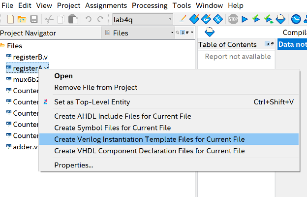
Here I'm making a template for registerA.
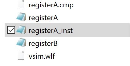
Quartus will output some info into the console, and then it is finished. It gives you almost no feedback about this, so it might seem like it did nothing.
In your windows file browser go to your project folder, you will see a new file called
<component_name>_inst.v, in my example it is called register_A_inst.v:
You can open this in your text editor of choice, then copy paste the verilog code part that is the template into whatever other component you need it:
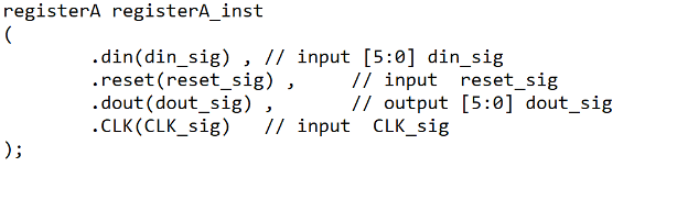
In this template you should change the instance name (registerA_inst
in the verilog code). Then you should replace the input names (they
all end in _sig in the verilog).
-
To create an array
fooof multi-bit registers, declare someregvariable like this example (which makes an arrayfoowhich is 8 16-bit registers):reg [15:0] foo [7:0];Here, the first set of brackets identifies the width of memory (bits per word), and the second identifies the depth (items in set). This is also done in the example memory verilog design above.
-
The
readmemhfunction assumes the inputmemory.txtfile is in hexadecimal (hence the "h" in the function name). Make sure your input file is in hex, or you can use the similar functions for other formats (e.g.readmemb).
Testing Tips:
-
The following verilog code may be helpful in creating test benches:
Verilog Test Bench Template
// use this if your design contains sequential logic parameter PERIOD = 20; parameter real DUTY_CYCLE = 0.5; initial // Clock process for CLK begin forever begin CLK = 1'b0; #(PERIOD-(PERIOD*DUTY_CYCLE)) CLK = 1'b1; #(PERIOD*DUTY_CYCLE); end end initial begin // Initialize Inputs // Wait one cycle for simulator to finish initializing #(PERIOD); // Enter test values end -
To display the simulation time when printing in a test bench, you can use the
$timespecial variable. For example:$display("At time %t, Q=%d", $time, Q); -
You can pause your simulation at the end of a test bench by adding the
$stopkeyword. Put this after your last test:initial begin //test inputs #(PERIOD); //check outputs $stop; endYou can use multiple of these keywords as breakpoints to pause the simulation after each test.
-
The
@function will cause your simulation to run until a specific signal takes on a certain value:Example use of
@initial begin //test inputs @(OUTPUT == 7); //simulation will keep running until the output signal is correct //check outputs //new inputs @(ALUout != 16'0011); //simulation runs until ALUout is no longer the specific number //check outputs $stop end
ModelSim Tips:
-
If you are missing windows, or they are organized strangely you can always go to
Layout > Resetto move everything back to where it started. -
While debugging you often want to change the radix of signals, hex is often easier to read than binary.
HOW TO: Change Radix of Signals
To change the radix select a signal, right click, go to the Radix option, and select how you want to
display the numbers. Think about when you want signed vs unsigned numbers!
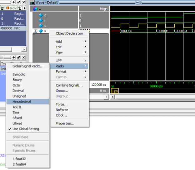
This screen shot shows the o signal being set to hexadecimal.
- By default ModelSim displays the full path name to each signal being simulated, this gets long and clunky and hard to read:
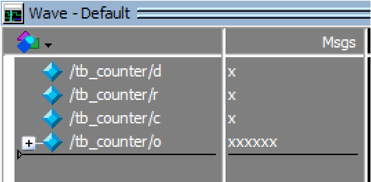
Notice every signal in this image starts with /tb_counter/.
HOW TO: Reduce Path Length in Display
We can eliminate this by clicking
inside the waveform window, on the top selecting the "Wave" menu, and going to "Wave Preferences".
Note: If your waveform is in a separate window, instead go to Tools > Window Preferences to get to the same place.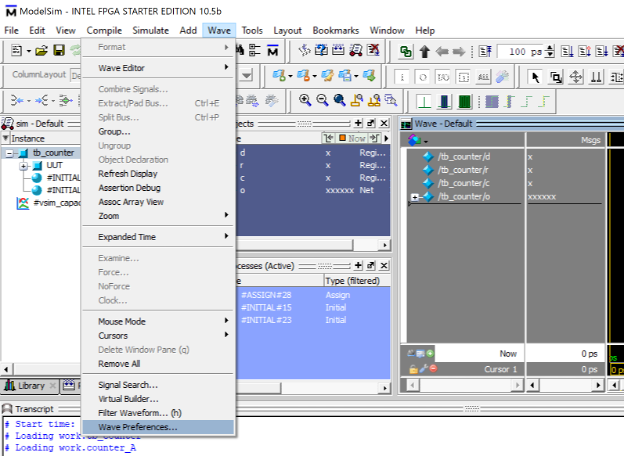
The Display Signal Path setting determines how deep the path name should go in the display: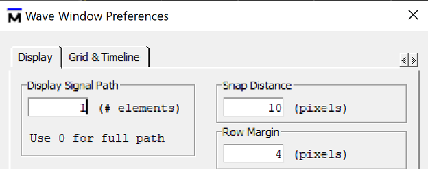
- 0 means "display the full path"
- 1 means "display only the signal name"
- 2 means "display the signal name, and the component it is a part of"
Early on you probably just want signal names, as the project gets larger you may want to change this to display more info.
This example sets the variable to a 1 therefore only the signal names show up in the waveform window now: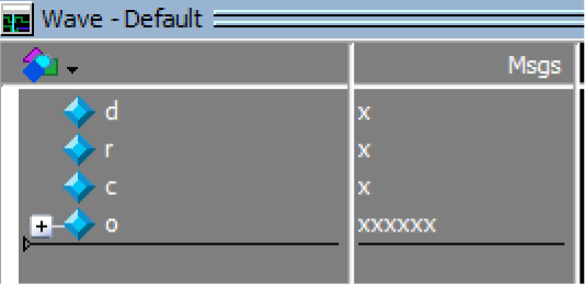
- When waveforms get full of many signals it can be hard to see individual wires, one thing that can help is changing the color of a particular signal.
HOW TO: Change Signal Colors
Right click a signal in the Wave window and go to "Properties":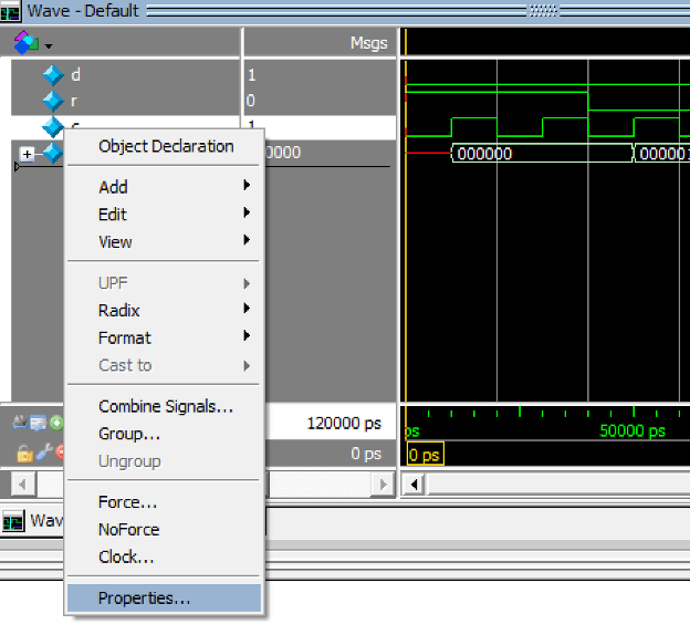
Press the "Colors" button and select a color for the signal (I used Yellow in this case):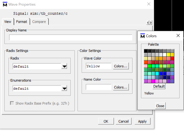
Then close the Color window, and press OK, the signal you selected will have the new color: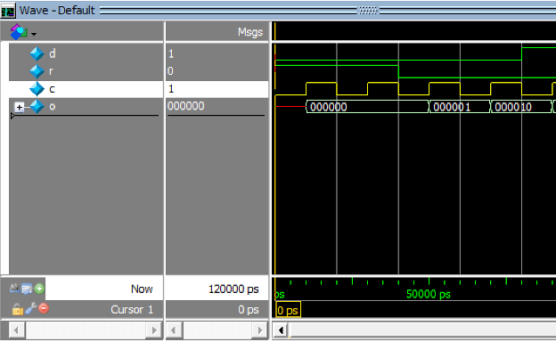
- When debugging it is often useful to investigate internal wires to larger components. DO NOT add extra outputs from components just to see them in the waveform.
HOW TO: Inspect internal signals
You can investigate components in the "sim" tab (in the same window that normally lists the files in the project)
after starting a simulation, and navigate to the component
that contains the wire you are interested in: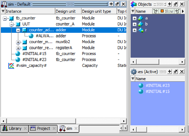
In this screenshot the counter_adder component is selected from inside of the UUT component.
Select the component that contains the signal you are interested in by left clicking. Its wires and reg's will
appear in the Objects window. You can right click these and add them to the waveform: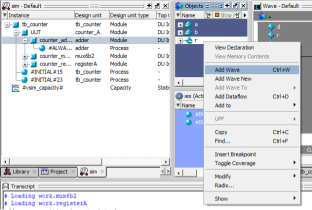
In this screenshot the r wire from inside the counter_adder component is being added to the waveform: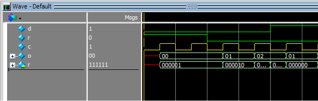
- It can be helpful to group signals in the waveform so you can hide signals you don't need during debugging.
HOW TO: Group Waveform Signals
Select a set of signals in the waveform (with shift or ctrl and click), right click and select
"Group", you can then name the group. Here is a sample waveform with various groups: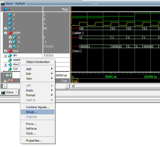
there is a group for the adder signals which is expanded, the mux signals are grouped but currently hidden,
and the register component's signals are currently selected and about to be added to a group.
- You often will need to work with the same waveform on several sessions or want to share your waveform with teammates.
HOW TO: Save and Restore Waveform configs
You can do this by clicking inside the Wave window and pressing Ctrl+S to save, this will pop up a save dialog:
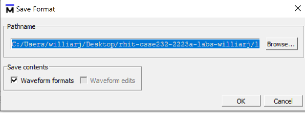
Name your waveform something useful, it should end in the ".do" file extention. You can then add this to your github repo and your teammates can pull it and load it into their model sim.
First, start the simulation on the appropriate component, then go to File > Load > Macro File...: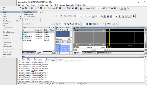
Select the ".do" file you want to load, you may need to change the "Files of type" setting to make it visible: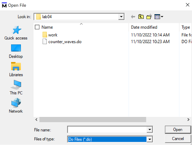
Press Open, and then run the simulation, your waveform should now have all the settings appropriately: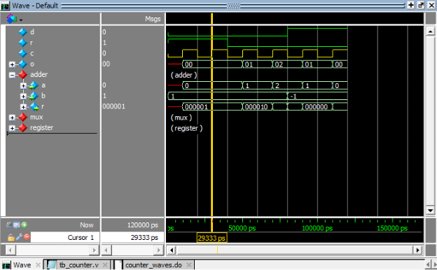
- You can change the Radix for memory, when you have the memory window open, right click in the window then select
Properties>Data Radixset it to hexadecimal.
8 Merge Conflicts (on Quartus Project files)
Merge conflicts will happen during development, they are not a bad thing, they are a sign of active and healthy work! This section will walk you through how to discard local changes to files you dont care about so that you can successfully pull from the repo.
NOTE: Doing this to any files totally DISCARDS local changes, with no way to get them back, so you should be careful about this with your verilog files. You can still follow these steps, just stop and think before you do so.
There is no danger of really harming the quartus project though, and conflicts on these files can be really annoying. A conflict can happen when two different users both change the same file. So, when do the project files change? There are 3 main times:
- You add new files to the project.
- You change the top-level entity on the project.
- You change some project settings.
These are really all trivial changes that can be reproduced, so no worry about "losing" any work if we did one of these and it caused a conflict.
If you do any of these things you should add, commit, and push the quartus project files to your repo.
NOTE: you really dont need to change the top-level entity, since we are only compiling in ModelSim for most of the quarter, just dont change it. In fact, you should not bother hitting the compile button in Quartus unless you absolutely have no other choice. Use ModelSim for debugging, not the very slow compile in Quartus.
So, I set up a quartus project called 'testing_gitignore'. I cloned this repo onto two different computers. On computer A I changed the top-level entity and then pushed my modified project files. On computer B I changed the top-level entity and then tried to pull, this caused this merge conflict:
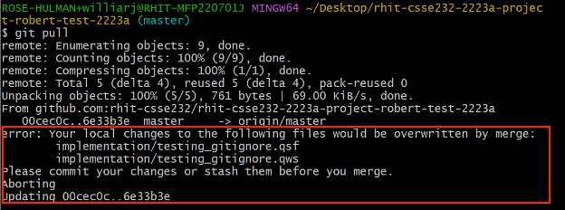
Note the error in the red box.
I realize this is not a big deal, I can simply discard my computer B changes to the project file and change the top-level entity again later, if I want to.
So, I will 'checkout' the last version of the project files from the repo. This essentially 'undoes' all the changes to the files that I made since the last time I pulled:
git checkout HEAD -- the/file/name/to/revert.txt

If I did this to Verilog files which I had edited, then those changes I had made since my last successful pull are lost forever. But in this case, I dont care about my changes to the project file.
Next, I pull as usual:
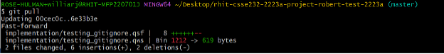
The project files updated and I can now open the quartus project and edit it as usual.