Lab 4 Testing Hardware
1 Objectives
Following completion of this lab you should be able to:
- Design robust tests for hardware components.
- Write verilog test benches.
- Read and interpret simulated waveforms.
2 General
- Get a copy of the question sheet to edit (Word doc version)
3 Setting up a project
- The module
The diagram below describes the component you will be testing in this lab.
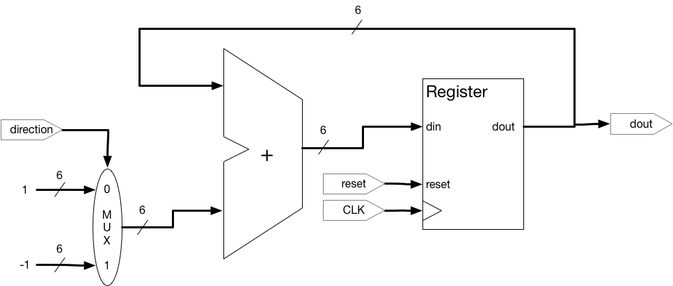
This component counts up or down based on the direction input. Every clock cycle the register data should update on the rising edge of the clock and the output should change at that time.
Your test bench should be concerned with these signals:
- direction - a 1 bit input that makes the component count up on 0 and down on 1
- CLK - the single bit clock input that updates the register on the rising edge
- reset - a single bit input that resets the counter's register to 0 on a rising edge
- dout - the 6 bit signed output from the component, this is the number stored in the register
Before you move on you should consider the behavior of this component and what sorts of errors might exist in the implementation of this component. Write down a list of possible errors on the answer sheet.
-
Setting up the Project
-
Start Quartus
-
Create a new project for this lab. Remember, details on how to do this can be found in Lab0.
-
Add the .v files from your Lab repo to the project.
-
Set Counter_A.v as the top module in the project, then compile the project once. NOTE: you may have to edit
Counter_A.vso the module name will match the uppercase C in the file name. -
Add a new test bench to the project, call it "tb_counter.v"
-
As the first line of the test bench, before anything (including
module), write:`timescale 1 ns/1 psDon't forget to include the single back-tick (
`) at the beginning of the line.Note that there is no semicolon at the end of the line above.
-
Create the module declaration for the test bench (no inputs or outputs necessary).
-
Set up the testbench file to instantiate an instance of "Counter_A" (the UUT).
- Make sure you create and name the testbench module itself.
- Set up (and comment) the variables for the input and output of the unit under test (UUT).
- Create an 'initial begin ... end' block where you will put the actual test code.
-
4 Writing Tests
-
Editing the test bench
Before we write tests we will set up the CLK input.
- We will specify the clock settings by adding a parameter at the top of the file. Below the Input and Output initialization add the following code:
parameter HALF_PERIOD = 50;

initial begin
    CLK = 0;
    forever begin
        #(HALF_PERIOD);
        CLK = ~CLK;
    end
end
Note that this code should be in a new
initialblock, not in the one you will write your test code in.- This creates a parameter
HALF_PERIODthat sets the length of the clock cycle. This number is arbitrary and is only used for simulation, it does not reflect the actual speed of the component in real hardware. Your tests should work even if this number is changed, so tests should use this parameter rather than hardcoded numbers. Do not hardcode any wait times in your tests!
This block initially sets the clock signal to 0, then starts an infinite loop that pauses for the length of HALF_PERIOD then inverts the clock.
-
In your testing block set up an initial value for all the inputs to 0, then put in a wait:
#(100*HALF_PERIOD)This will wait for 50 clock cycles after your initial inputs. -
To confirm that your clock is set up correctly start ModelSim, set up a project for testing these components, and start a simulation of the testbench. Make sure your simulation waveform shows all the inputs and outputs for the UUT and the clock signal you set up above. You should see the clock ticking up and down at regular 50 ns intervals.
-
You might notice the output signal from the UUT is
XXXXXthis means the signal was never initialized and needs to be set up properly. This is because the component needs to receive theresetsignal to initialize it. -
Go back to your test bench and in the testing block code change the starting value for the reset input to 1:
reset = 1;, then after the 50 cycle wait you added earlier change reset back to 0. Add another wait after this for another 50 cycles. Once you've made these modifications go back to ModelSim, recompile the files and re-run the test. -
You should now see reset starts off at 1 and after 50 cycles goes to 0.
doutshould have a value of 0 for the first 50 cycles and then should start ticking up.
-
Writing the first test.
This section will guide you through writing a single test for the component as an example of the kind of considerations you should make. A few things you should keep in mind:
- Tests should be reproducible.
- Failures should be loud.
- Which test caused a failure should be obvious.
- Tests should isolate errors.
To these ends our tests will be well documented and they should not depend on a human noticing a failure in the waveform. Therefore, "we looked at the waveform for confirmation" is not a valid test. Additionally, we want our tests to be as specific as possible, we should not rely on one test that fails for a many different reasons. Every unique error should cause a unique set of tests to fail.
- We'll probably want a few helper variables for our tests, lets set those up. Below where you set up the
HALF_PERIODparameter create three variables:
integer cycle_counter = 0;
integer counter = 0;
integer failures = 0;
We'll use these in each of our tests to help track down errors. Note:
integersandparametersin verilog should only be used in test fixtures, do not include them in any components you write in the future.- Inside the testing block, add a comment that marks an area for the first test and describes the test, as well as a print to the console so we can see the test ran in the simulation:
//-----TEST 1----- //Testing counting up $display("Testing counting up.");- The first thing we want to do in every test is reset the inputs to what this test requires. We should do this even if a variable has not changed from a previous test (we might reorder tests in the future!). So lets set the inputs up for the test right after the display statement:
reset = 1;
counter = 0;
cycle_counter = 0;
#(2*HALF_PERIOD);
reset = 0;
direction = 0; //we are testing counting up
We set
reset1 and wait a single clock cycle and then setdirectionandresetto 0. This is so we know the state of the machine at the beginning of the test: It should have 0 in the register and should start counting up.-
Add a line that will wait for 50 clock cycles after the input initialization so we can investigate the waveform.
-
Next, lets set up an output that will tell us our tests have finished and how many failures occurred. At the end of the testing block add the following line:
$display("TESTS COMPLETE. \n Failures = %d", failures);
$stop;
The
$stopline will pause the simulation when it gets to that point, so ModelSim doesn't keep running forever. This essentially acts as a breakpoint and you can include several in your test benches.-
Save your test and run the simulation. Investigate the output and make sure the behavior makes sense to you.
-
Now lets actually write a test that ensures the counter goes up by one every single clock cycle. We need to consider the device we are testing, what is the largest and smallest number our counter can contain? What happens if it tries to keep counting once it goes past the maximum? Its important to remember that the adder in our component uses signed numbers (it can take in a -1, after all), so the output from the adder will be signed as well. We need to indicate in our testbench that the number in our register is signed, therefore edit the output line to read:
wire signed [5:0] dout. -
Lets make a loop that will count up to that maximum and a few extra cycles so we can test the overflow behavior, put this right after the
direction = 0line we added:
repeat (40) begin #(2*HALF_PERIOD); counter = counter + 1; cycle_counter = cycle_counter + 1; if (dout != counter) begin failures = failures + 1; $display("%t (COUNT UP) Error at cycle %d, output = %d, expecting = %d", $time, cycle_counter, dout, counter); end end-
Look at this code and explain briefly what it does in your own words.
-
It is a good idea to make sure messages are labeled with information about which test they are associated with. Here our code outputs (COUNT UP) in all messages about this test. It also uses the
$timevariable to output the time during the simulation that the message was printed, this will help you track down where in a waveform an error occurred. Use this output to figure out what time in the simulation cycle 23 of this test occurs, you may need to modify the code or use the waveform. -
Your output should include some failed tests, explain why this is happening. If your output doesn't include any failed tests, then you probably didnt read step #7 above carefully.
-
These failures are not a problem with our component, but an issue with our test not accurately testing the true behavior of the module. Lets modify the test a bit by keeping track of when we have overflowed the register:
repeat (40) begin
    #(2*HALF_PERIOD);
    counter = counter + 1;
    if (cycle_counter == 31)
         counter = -32;
    cycle_counter = cycle_counter + 1;
    if (dout != counter) begin
       failures = failures + 1;
       $display("%t (COUNT UP) Error at cycle %d, output = %d, expecting = %d", $time, cycle_counter, dout, counter);
    end
end
Run this new test, explain what it is doing.
- When debugging components you will need to investigate the waveforms and look for places where unexpected behavior is happening. Here are a few things you should practice:
- Change the radix (the base) of numbers in the waveform: right click a signal, Radix > select the base you want
- Group signals together: select multiple signals with ctrl+click > right click > group > name the group
- Locate wire from an inner component inside the module and add it to the waveform: navigate to the component in the objects pane, right click > add wave. After adding a new signal you will need to reset and resimulate. [Practice this by displaying the selector bit for the mux used inside the Counter component in the waveform.]
5 Testing other components
You have been provided with several different implementations of the counter component described above. All but one of them are implemented in a way that does not meet the specifications. You should not edit any of these module components. The only work you will do in this lab is in the test bench you created above.
We now have a test and configuration file that will confirm that a component correctly counts up by one each clock cycle. Lets test some of the other versions of the components in the project.
To find these errors what you should do is run your test on each component, investigate the waveform, and try to track down where the errors occur. You should compare the waveform for Counter_A (which has no errors) with each of the others. You may need to investigate internal wires to figure out the source of the problem.
-
Open up "tb_counter.v" locate the line that initializes the UUT. Lets test a different component, all of our components have the same structure to their constructor, so we just need to call a different module (the equivalent to just changing the Class of the object you are constructing in Java). Change "counter_A" to "counter_B", save the test and run the simulation.
-
Investigate the waveform and the output of your test. Does it pass your test?
-
You can run each of the other counter implementations through your test if you would like.
6 Write more tests
-
Your job for this lab is to expand your test bench such that it can find the errors in all of the implementations of the counters you have been provided.
-
You may want to explore the Resources page of the course website for more tips about test bench writing, waveforms, and working with ModelSim.
-
The only signals your tests can use or manipulate are the top-level inputs and outputs to the counter module (direction, reset, CLK, dout). All your tests should manipulate or observe these signals in order to detect errors. (Hint: if you look at the waveform, how is it "broken"?)
-
You should end up with at least one test per error you find in the counters. All the counters have a unique error, so you should have at least 4 unique tests.
-
Any one counter might fail multiple tests, but the combination of failed tests should help us pinpoint the exact error in the component.
-
After you have written all of your tests write a brief explanation of how each component is broken and which of your tests detects the error.
-
Remember to reset all of your inputs and parameters between each test.
-
Some of these modules have very subtle errors that you will need to carefully design tests to detect.
-
You should only create a single test fixture that can run any one of the modules, do not make different files for each one.
7 Turning It In
Submit the answers to the questions contained in the lab guide using the question sheet via gradescope, only 1 per team (make sure all team member's names are included). In gradescope you are able add your team members names to the submission, make sure you do so. When you are prompted to indicate where the "code question" is on the answer sheet, just select the first page of the assignment, you DO NOT upload code to gradescope.
Submit your test bench (tb_counter.v) to ALL team member's git repositories in the lab04 directory. Do NOT commit the full Quartus project, only add the new test fixture to the repo. No other verilog files should have been changed.