Writing Verilog Testbenches
Writing a testbench is technically straightforward. As covered in lecture, you:
- declare
regsfor inputs andwiresfor output, - instantiate your Unit Under Test (
UUT) module, - run stimulus in an
initial beginblock, setting the inputregs, wait for a proper amount of time, and observe the outputwireto see if it matches with the expected value(s).
For instance, we want to test whether our 32-bit ALU module performs addition correctly. Our testbench will follow the three steps listed above:
module tb_ALU();
    // 1. input regs and output wires
    reg[31:0] A, B;
    reg[3:0] ALUOperation;
    wire[31:0] ALUOut;

    // 2. instantiate ALU module
    ALU UUT( // Unit Under Test
        .operation(ALUOperation),
        .din_a(A),
        .din_b(B),
        .dout(ALUOut),
    );

    // 3. run stimulus and check result
    initial begin
        // set ALU inputs for 1+1 test
        A = 32'h00000001;       // A = 1
        B = 32'h00000001;       // B = 1
        ALUOperation = 4'b0000; // add operation

        // wait proper amount of time for signal to propergate
        #5;

        // check outputs to see if they have the expected outputs
        if (ALUOut == 32'h00000002) begin
            $display("ALU 1+1=2 passed");
        end
        else begin
            $display("ALU 1+1=2 failed")
        end

        $stop;
    end
endmodule;
Note that we are ignoring the zero port in the ALU from ALU.v in Pracitcal 6 for brevity.
That's it right? We have a working processor?
Evidently, this is insufficient as it the test cases do not provide enough coverage to give us confidence that the ALU is working in its entirety.
Then, what does such a testbench look like? How do we write a testbench that will convince us the module is fully funcitonal? The brute force solution is to run every single possible input combination. But, this is more often than not way too tedious; in our case, that is $2^{32} \cdot 2^{32} \cdot 9 \approx 2^{67}$ inputs ($\cdot 9$ because our ALU module only has 9 valid ALU Operations).
We need to strike a sweet spot. We need to write a minimally sufficient set of test cases: sufficient meaning we test all the possible standard and edge case behaviors of the module (e.g., what about summing negative numbers? A positive and negative number? Vice Versa?); minimal meaning we don't want too much redundancy in what we are testing (e.g., testing 1+1 and 2+2 are functionally equivalent for our testing purposes).
This guide will take you through the design process of creating a sufficiently rigourous testbench. But before we do so...
The vunit Testing Framework
Practical 4, introduces the vunit testing framework. This is a custom framework for CSSE232 that makes fuller use of ModelSim's features. Some of this should have been demoed in class, but here is a more thorough walkthrough of how to use this framework.
This guide will also take you through some VSCode shortcuts that will significantly reduce your testbench writing time. By significant, I really mean significant. At the very least, read through this guide and make sure you know how to efficiently use VSCode along with vunit.
A Funky ALU for Demo Purposes
To model the majority of testbenches you will be writing Practical 5 through Practical 9, we will assume a clocked ALU. A clocked ALU is by all means funky, but this will allow a more thorough tutorial of how test clocked components. From here onwards, we will assume the ALU is clocked to the rising edge, meaning ALUOut is produced on posedge.
Remember, this is for tutorial demo purposes only. If you assume the ALU is clocked in your processor, your timing will be chaotically off.
To implement this, we'll need a .clock() port in our ALU module, as well as create a perpetual running clock CLK in our testbench:
module tb_ALU();
    // 1. input regs and output wires
    reg[31:0] A, B;
    reg[3:0] ALUOperation;
    wire[31:0] ALUOut;

>   // 1.5 create a perpetual clock
>   // create a clock
>   reg CLK;
>   parameter HALF_PERIOD = 50;
>   initial begin
>       CLK = 1;
>       forever #(HALF_PERIOD) CLK = ~CLK;
>   end

    // 2. instantiate ALU module
    ALU UUT( // Unit Under Test
        .operation(ALUOperation),
        .din_a(A),
        .din_b(B),
        .dout(ALUOut),
>       .clock(CLK)  // for demo purposes only
    );
endmodule;
Additionally, "wait proper amount of time" is no longer simply waiting #5 nanoseconds. Instead, we need to wait for posedge CLK and negedge CLK in our stimulus step:
module tb_ALU();

    // 3. run stimulus and check result
    initial begin
        // set ALU up with undefined values to act as "reset" for a full cycle
        A = 32'hx;
        B = 32'hx;
        ALUOperation = 4'bx;
        @(posedge CLK); // wait for next posedge
        @(negedge CLK); // wait for next negedge

        // set ALU inputs for 1+1 test
        A = 32'h00000001;       // A = 1
        B = 32'h00000001;       // B = 1
        ALUOperation = 4'b0000; // add operation

        @(posedge CLK);         // ALU performs addition
        #1;                     // wait a lil for prop delay to reach output wire
        if (ALUOut = 32'h00000002) begin
            $display("ALU 1+1=2 passed");
        end
        else begin
            $display("ALU 1+1=2 failed");
        end

        $stop;
    end
endmodule;
Notice that for clocked components, the tests will always follow the structure of 1) set input values, 2) waiting for the proper clock edge, 3) waiting a small bit of additional time for the signals to propogate, and 4) check the output wire results.
vunit Setup:
Firstly, we'll need to set up the framework with VU.INITIALIZE_TESTS() and VU.END_REPORT(); in initial begin
module tb_ALU();
    // 3. run stimulus and check result
    initial begin
>       VU.INITIALIZE_TESTS();

        // set ALU up with undefined values to act as "reset" for a full cycle
        A = 32'hx;
        B = 32'hx;
        ALUOperation = 4'bx;
        @(posedge CLK); // wait for next posedge
        @(negedge CLK); // wait for next negedge

        // set ALU inputs for 1+1 test
        A = 32'h00000001;       // A = 1
        B = 32'h00000001;       // B = 1
        ALUOperation = 4'b0000; // add operation

        @(posedge CLK);         // ALU performs addition
        #1;                     // wait a lil for prop delay to reach output wire
        if (ALUOut = 32'h00000002) begin
            $display("ALU 1+1=2 passed");
        end
        else begin
            $display("ALU 1+1=2 failed");
        end

>       VU.END_REPORT();
        $stop;
    end
endmodule;
All this does is set up the variables used in vunit to keep track of test name, test count, and error counts.
The First vunit Test and Assert
Let's now make use of vunit in the above testbench running 1+1. This will only affect the initial begin block. In this case, we'll utilize VU.SET_TEST_NAME() and VU.ASSERT_INT_EQUAL in place of the if/else conditionals and display statements:
module tb_ALU();
    // 3. run stimulus and check result
    initial begin
        VU.INITIALIZE_TESTS();

        // set ALU up with undefined values to act as "reset" for a full cycle
        A = 32'hx;
        B = 32'hx;
        ALUOperation = 4'bx;
        @(posedge CLK); // wait for next posedge
        @(negedge CLK); // wait for next negedge

        // set ALU inputs for 1+1 test
        A = 32'h00000001;       // A = 1
        B = 32'h00000001;       // B = 1
        ALUOperation = 4'b0000; // add operation

        @(posedge CLK);         // ALU performs addition
        #1;                     // wait a lil for prop delay to reach output wire
>       VU.SET_TEST_NAME("ALU 1+1=2 ALUOut test // ALUOut <- 2")
>       VU.ASSERT_INT_EQUAL(ALUOut, 32'h00000002);

        VU.END_REPORT();
        $stop;
    end
endmodule;
Note that the test still has the same structure of 1) set input values, 2) waiting for the proper clock edge, 3) waiting a small bit of additional time for the signals to propogate, and 4) check the output wire results. Instead here the vunit functions allow for more streamlined test case writing, as well as automated test pass/fail counts in ModelSim.
Writing a Sufficiently Rigorous Addition Testbench
Testing for 1+1=2 does not give us the confidence that our ALU will perform addition correctly every single time. Remember, we want to strike the sweet spot of a minimally sufficient set of tests. 1+1=2 is a good start, but it's lacking:
- only uses the first bit of a 32'bit input
- no negative numbers tested for summation
Let's build out more test cases then! First, let's make a test case that every bit of the 32-bit input can sum correctly. We'll do this by summing 0xFFFFFFFF with 0x00000000 and vice versa.
module tb_ALU();
    // 3. run stimulus and check result
    initial begin
        VU.INITIALIZE_TESTS();

        // set ALU up with undefined values to act as "reset" for a full cycle
        A = 32'hx;
        B = 32'hx;
        ALUOperation = 4'bx;
        @(posedge CLK); // wait for next posedge
        @(negedge CLK); // wait for next negedge

        // set ALU inputs for 1+1 test
        A = 32'h00000001;       // A = 1
        B = 32'h00000001;       // B = 1
        ALUOperation = 4'b0000; // add operation, doesn't change across tests

        @(posedge CLK);         // ALU performs addition
        #1;                     // wait a lil for prop delay to reach output wire
        VU.SET_TEST_NAME("ALU 1+1=2 ALUOut test // ALUOut <- 2")
        VU.ASSERT_INT_EQUAL(ALUOut, 32'h00000002);

>       // set ALU inputs for 0xffffffff+0 test
>       A = 32'hffffffff;       // A = -1
>       B = 32'h00000000;       // B = 0

>       @(posedge CLK);         // ALU performs addition on next posedge
>       #1;                     // wait a lil for prop delay to reach output wire
>       VU.SET_TEST_NAME("ALU 0xFFFFFFFF + 0 ALUOut test // ALUOut <- -1")
>       VU.ASSERT_INT_EQUAL(ALUOut, 32'hffffffff);

>       // set ALU inputs for 0+0xffffffff test
>       A = 32'h00000000;       // A = 0
>       B = 32'hffffffff;       // B = -1

>       @(posedge CLK);         // ALU performs addition on next posedge
>       #1;                     // wait a lil for prop delay to reach output wire
>       VU.SET_TEST_NAME("ALU 0 + 0xFFFFFFFF ALUOut test // ALUOut <- -1")
>       VU.ASSERT_INT_EQUAL(ALUOut, 32'hffffffff);

        VU.END_REPORT();
        $stop;
    end
endmodule;
Let's also add the test cases for the ALU summing combinations of positive/negative numbers correctly. 1+1=2 covers the positive + positive case, so we'll need a total of 4 cases:
1 + 1 = 2for positive + positive32 + -16 = 16for positive + negative case-32 + 16 = -16for negative + positive case-32 + -32 = -64for negative + negative case
So let's add these 4 tests into our testbench...
VSCode Hotkeys to Save Writing Time
...or not. There should be a flicker of hesitation when you read that we're going to write 4 more test cases. From the previous code snippit, each additional test case is 7 more lines, so that's going to be 28 more lines. Even if you have great typing speed, that's still quite a bit of typing!
If the thought "well this is going to be tedious..." crossed your mind, that's normal and good! Here we are going to cover how to use some nifty VSCode hotkeys to produce multiple test cases simultaneously.
First, we have to plan out our inputs all in a single place. We already have:
    A = 32'h00000001; // A = 1
    B = 32'h00000001; // B = 1
    A = 32'hffffffff; // A = -1
    B = 32'h00000000; // B = 0
    A = 32'h00000000; // A = 0
    B = 32'hffffffff; // B = -1
Let's add in the other 4 test cases we just came up with. Let's also make this a bit more human friendly and use decimal instead of hex. We don't have to fully commit to binary/hex in our test case writing. Note the syntax for declaring decimals and/or negative numbers in Verilog:
- Declare the base:
32'hmeans "32-bit hex",32'dmeans "32-bit decimal" - Declare the sign: by default Verilog reads
32'das "32-bit unsigned decimal," we'll want32'sdfor "32-bit signed decimal"
>   A = 32'sd1;         // A = 1
>   B = 32'sd1;         // B = 1
>   A = 32'sd32;        // A = 32
>   B = -32'sd16;       // B = -16
>   A = -32'sd32;       // A = -32
>   B = 32'sd16;        // B = 16
>   A = -32'sd32;       // A = -32
>   B = -32'sd32;       // B = -32
    A = 32'hffffffff;   // A = -1
    B = 32'h00000000;   // B = 0
    A = 32'h00000000;   // A = 0
    B = 32'hffffffff;   // B = -1
As additional preparation, let's add in a few additinal details in this planning file, such as the test name and expected output
    A = 32'sd1;         // A = 1    ALU pos+pos test // ALUOut <- 2
    B = 32'sd1;         // B = 1
    A = 32'sd32;        // A = 32   ALU pos+neg test // ALUOut <- 16
    B = -32'sd16;       // B = -16
    A = -32'sd32;       // A = -32  ALU neg+pos test // ALUOut <- -16
    B = 32'sd16;        // B = 16
    A = -32'sd32;       // A = -32  ALU neg+neg test // ALUOut <- -64
    B = -32'sd32;       // B = -32
    A = 32'hffffffff;   // A = -1   ALU 1's + 0's test // ALUOut <- -1
    B = 32'h00000000;   // B = 0
    A = 32'h00000000;   // A = 0    ALU 0's + 1's test // ALUOut <- -1
    B = 32'hffffffff;   // B = -1
This planning file is a lot easier to produce than direclty writing lines of Verilog. As a general rule, careful planning will always make you more efficient.
Back to the Verilog testbench. We have a total of 6 tests. Let's copy-paste 6 sets of test blanks using the vunit framework:
module tb_ALU();
    // 3. run stimulus and check result
    initial begin
        VU.INITIALIZE_TESTS();

        // set ALU up with undefined values to act as "reset" for a full cycle
        A = 32'hx;
        B = 32'hx;
        ALUOperation = 4'bx;
        @(posedge CLK); // wait for next posedge
        @(negedge CLK); // wait for next negedge

>       // set ALU inputs
>       A = 32'hxxxxxxxx;       // A = x
>       B = 32'hxxxxxxxx;       // B = x
>       @(posedge CLK);
>       #1;
>       VU.SET_TEST_NAME("Test name")
>       VU.ASSERT_INT_EQUAL(ALUOut, 32'hxxxxxxxx);

>       // set ALU inputs
>       A = 32'hxxxxxxxx;       // A = x
>       B = 32'hxxxxxxxx;       // B = x
>       @(posedge CLK);
>       #1;
>       VU.SET_TEST_NAME("Test name")
>       VU.ASSERT_INT_EQUAL(ALUOut, 32'hxxxxxxxx);

>       // set ALU inputs
>       A = 32'hxxxxxxxx;       // A = x
>       B = 32'hxxxxxxxx;       // B = x
>       @(posedge CLK);
>       #1;
>       VU.SET_TEST_NAME("Test name")
>       VU.ASSERT_INT_EQUAL(ALUOut, 32'hxxxxxxxx);

>       // set ALU inputs
>       A = 32'hxxxxxxxx;       // A = x
>       B = 32'hxxxxxxxx;       // B = x
>       @(posedge CLK);
>       #1;
>       VU.SET_TEST_NAME("Test name")
>       VU.ASSERT_INT_EQUAL(ALUOut, 32'hxxxxxxxx);

>       // set ALU inputs
>       A = 32'hxxxxxxxx;       // A = x
>       B = 32'hxxxxxxxx;       // B = x
>       @(posedge CLK);
>       #1;
>       VU.SET_TEST_NAME("Test name")
>       VU.ASSERT_INT_EQUAL(ALUOut, 32'hxxxxxxxx);

>       // set ALU inputs
>       A = 32'hxxxxxxxx;       // A = x
>       B = 32'hxxxxxxxx;       // B = x
>       @(posedge CLK);
>       #1;
>       VU.SET_TEST_NAME("Test name")
>       VU.ASSERT_INT_EQUAL(ALUOut, 32'hxxxxxxxx);

        VU.END_REPORT();
        $stop;
    end
endmodule;
Now for some VSCode hotkeys: crtl+d. If you highlight any string in VSCode and press crtl+d, VSCode will highlight the next instance of the string. This will also give you an additional cursor that you can type or copy-paste in parallel. We will use this to our advantage.
-
Let's look for patterns in our testbench that we can copy-paste into.
The first set are the input declarations for
A=andB=. The common pattern is the 12 lines of32'hxxxxxxxx;. Note that we are including the semi-colon;. If we do not, VSCode will highlight the32'hxxxxxxxxin theASSERTstatement as well. -
Let's copy the 12 lines that we want to paste to replace
32'hxxxxxxxx;. In the planning file, highlight the string32':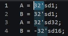
Notice VSCode trying to be helpful and highlighting all instances of
32'in a lighter shade. This means we're all set to usecrtl+d. Press and hold downcrtl+dand watch VSCode fly through all other instances of32':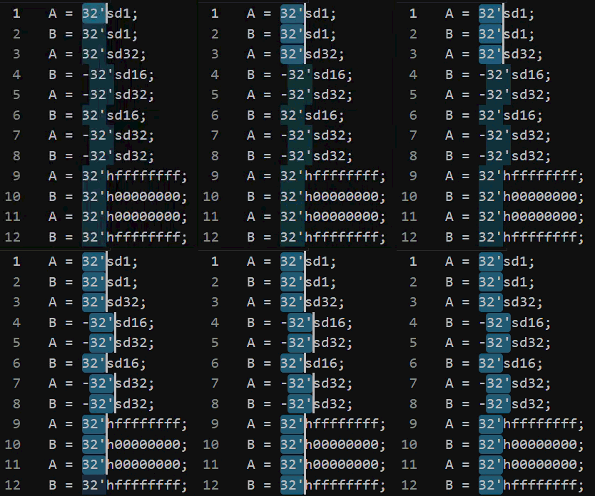
VSCode will now have 12 blinking cursors. If you try to type right now, VSCode will insert text on all 12 lines simultaneously. Let's say for instance we want to change all the tests from 32-bits to 16-bits. Then we can backspace and type in
16'all at once.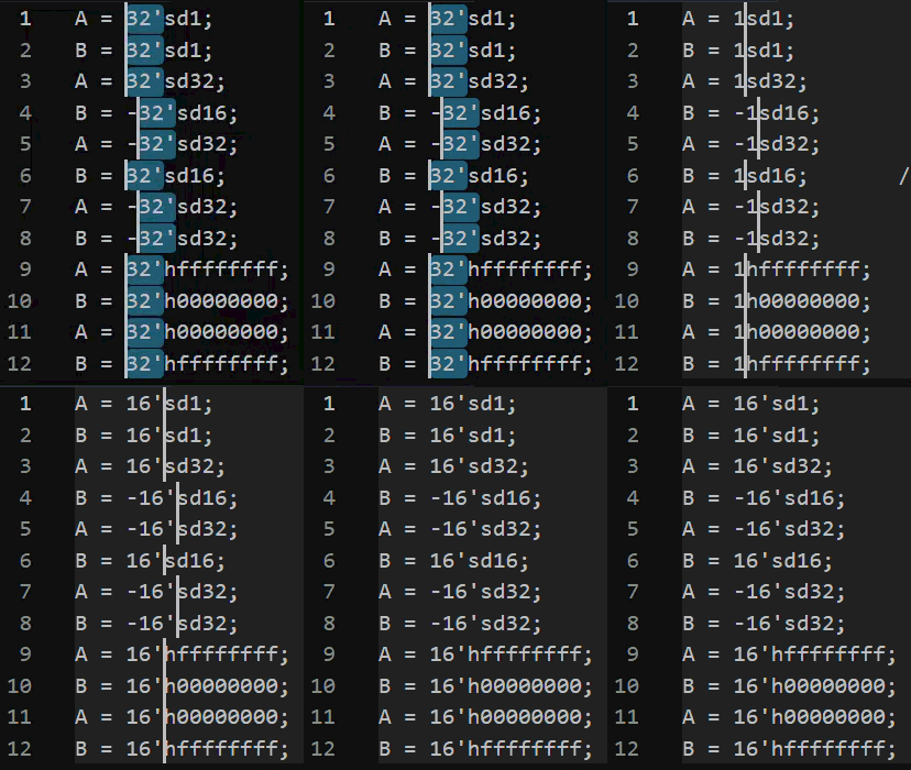
This is equivalent to a Find-and-Replace, but in a more narrow scope with more control. But this not the only use of this feature.
What we want is to paste all 12 lines of
A =andB =into our testbench. We have to get a bit creative with how we use this hotkey.Starting with all instances of
32'highlighted, we will input the following keyboard inputs:-
hometo move all cursors to the start of the line, -
crtl+shift+right arrow5 times to highlight the strings that we want: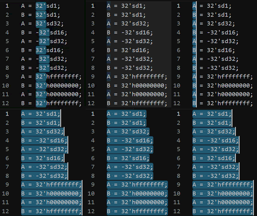
-
And now
crtl+cto copy these 12 strings onto the clipboard.In VSCode, highlight
32'hxxxxxxxx;once, then press and holdcrtl+dto highlight all 12 instances of32'hxxxxxxxx;, use thehome+crtl+shift+right arrowto highlight the strings to replace, and finally presscrtl+vand watch all 12 input statements be pasted into their respective places: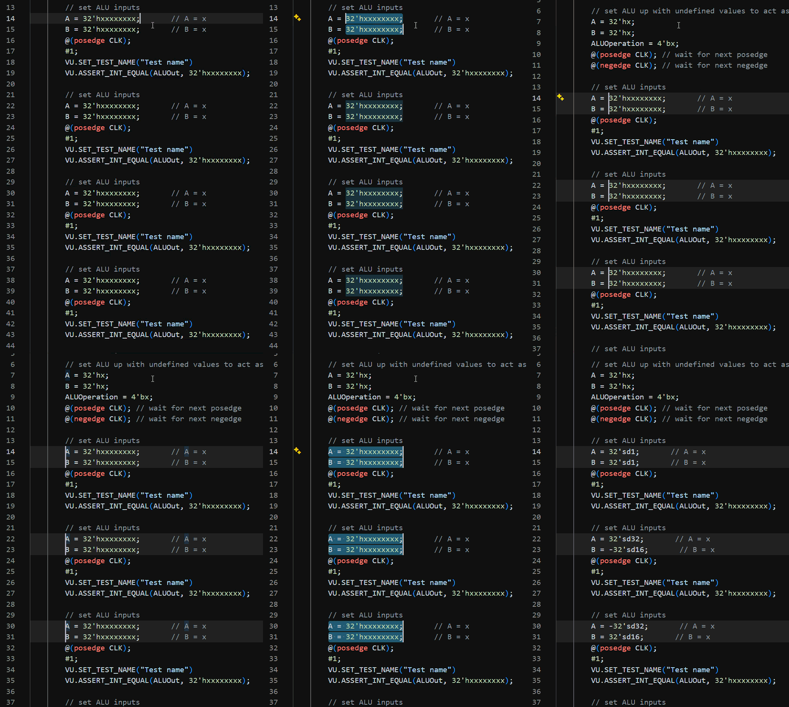
And there you go! All 6 test case inputs copy and pasted at once. No need to type them in one-by-one into Verilog.
-
-
Repeat the same steps for the other parts of the testbench: the comments, test name, and output values for the
ASSERT.With a bit of practice for both using the
crtl+dhotkey as well as figuring out which string patterns to use, you can write test benches very efficiently:
Remaining Edge Cases Tests
We now have 6 tests for the addition testbench. 4 tests covering positive/negative combinations, and 2 tests that makes sure all 32 bits behave correctly for addition.
Did we build a robust test? Did we meed minimally sufficiency?
There's no explicit to test, but you want to take a few moments to think through other possible edge cases.
student.think(30 seconds);In this case, we do! What about register overflow/underflow? What about the upper and lower bounds of 32-bit values? Let's add these additional cases:
    A = 32'sd1;           // A = 1    ALU pos+pos test // ALUOut <- 2
    B = 32'sd1;           // B = 1
    A = 32'sd32;          // A = 32   ALU pos+neg test // ALUOut <- 16
    B = -32'sd16;         // B = -16
    A = -32'sd32;         // A = -32  ALU neg+pos test // ALUOut <- -16
    B = 32'sd16;          // B = 16
    A = -32'sd32;         // A = -32  ALU neg+neg test // ALUOut <- -64
    B = -32'sd32;         // B = -32
    A = 32'hffffffff;     // A = -1   ALU 1's + 0's test // ALUOut <- -1
    B = 32'h00000000;     // B = 0
    A = 32'h00000000;     // A = 0    ALU 0's + 1's test // ALUOut <- -1
    B = 32'hffffffff;     // B = -1
>   A = 32'hfffffffe;     // A = -2   ALU overflow test // ALUOut <- 1
>   B = 32'h00000003;     // B = 3
>   A = 32'h00000001;     // A = 1    ALU underflow test // ALUOut <- -1
>   B = 32'hfffffffe;     // B = -2
>   A = 32'sd4294967295;  // A = 2^32-1 ALU max value test // ALUOut <- -4294967296
>   B = 32'sd1;           // B = 1
>   A = -32'sd4294967296; // A = -2^32 ALU min value test // ALUOut <- 4294967295
>   B = -32'sd1
There's no checklist to follow to determine whether you've built a sufficiently robost test. It will be up to intuition, experience/practice, and spending adequate time pondering edge cases.
This skill is important to hone! This is the same skillset you use when you are writing proofs and finding counterexamples, designing secure systems by identifying potential sources of vulnerability, or imagining stress cases for human users when they use your software product.
crtl+d Copy-Paste Precautions
Those diligent enough to be following this guide and implementing/testing this on your machine, you'll likely bump into the issue that ModelSim's waveform is horrendously undefined with the dreaded red signals.
Why is this the case? Didn't we plan our test cases carefully?
Yes, we did plan the test cases carefully, but we were not careful in implementing the testbench. In copy-pasting the test case blanks:
    // set ALU inputs
    A = 32'hxxxxxxxx;       // A = x
    B = 32'hxxxxxxxx;       // B = x
    @(posedge CLK);
    #1;
    VU.SET_TEST_NAME("Test name")
    VU.ASSERT_INT_EQUAL(ALUOut, 32'hxxxxxxxx);
We've neglected the fact that ALUOperation neesd to be set to 4'b0000 to instruct the ALU to perform the summation. We'll need to set ALUOperation = 4'b0000 once in the beginning after the rest.
This is a common pitfall of writing test cases in this manner. In focusing on finding patterns and slotting in the test case strings, we ended up tunnelvision-ing and forgot about ALUOperation.
Take the proper precautions writing your testbenches, and debug using ModelSim's error messages diligently!
Modularizing Testbenches
Now that we've tested ALU's add operation and we're confident in its behavior, let's move on to subtraction!
Instead of throwing in more test cases into our initial begin block, let's modularize our testbench by declaring tasks. This operates in the same way as a void function in C or Java.
task test_addition();
begin
    // set ALU up with undefined values to act as "reset" for a full cycle
    A = 32'hx;
    B = 32'hx;
    ALUOperation = 4'bx;
    @(posedge CLK); // wait for next posedge
    @(negedge CLK); // wait for next negedge

    // set ALU inputs
    A = 32'sd1;       // A = 1
    B = 32'sd1;       // B = 1
    ALUOperation = 4'b0000; // add operation, doesn't change across tests
    @(posedge CLK);
    #1;
    VU.SET_TEST_NAME("ALU pos+pos test // ALUOut <- 2")
    VU.ASSERT_INT_EQUAL(ALUOut, 32'sd2);

    // set ALU inputs
    //...
end
endtask

initial begin
    VU.INITIALIZE_TESTS();

>   test_addition();
    // test_subtraction();

    VU.END_REPORT();
    $stop;
end
This way, you get to build and test modularly, allowing for better organization, debugging, and division of tasks!
Revisiting Your Assembler
You may have noticed that the planning file that contains just the inputs is quite similar to the output .asm files your assembler produces back in Practical 1 and Practical 2.
This is incentive for you to revisit Practicals 1 and 2 and apply any tweaks to the formatting of the output .asm file so that it will allow you quickly convert it into a Verilog testbench. For instance, a .asm file of:
0100 0001 1111 1000 0000 0010 1011 0011 //;;; 0x41f802b3 ;;; 0x400024 -     sub x5, x16, x31
0100 0000 1010 0000 0000 0100 0011 0011 //;;; 0x40a00433 ;;; 0x400028 -     sub s0, zero, a0
0000 0001 1111 0000 0100 0001 1011 0011 //;;; 0x01f041b3 ;;; 0x40002c -     xor x3, x0, at
May not be formatted in a way desirable for quick conversion into a testbench. As you work on the testbench for your processor Practical 6 onwards, you may choose to tweak the output format to best help you build testbenches.
You might instead want something formatted like:
41f802b3 // sub x5, x16, x31    ;;; x5 <- 5
40a00433 // sub s0, x0, x10     ;;; s0 <- -1
01f041b3 // xor x3, x0, x31     ;;; x3 <- 10
Go and customize the assembler and make it your own!