Chapter 4: Electricity and Magnetism Experiments
Magnetic Field Mapping
References
Crummett and Western, Physics: Models and Applications,
Sections
Halliday, Resnick, and Walker Fundamentals of Physics (5th
ed.), Section 30-5
Tipler, Physics for Scientists and Engineers (3rd ed.), Section
Introduction
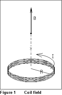 Whenever an
electric current flows in a conductor, a magnetic field is created in the
space around it. One of the fundamentally important arrangements is a circular
coil. If a current I flows in a coil of N turns of wire,
each of radius R, the magnetic field produced on the axis of the coil,
at a distance x from its center, is given by
Whenever an
electric current flows in a conductor, a magnetic field is created in the
space around it. One of the fundamentally important arrangements is a circular
coil. If a current I flows in a coil of N turns of wire,
each of radius R, the magnetic field produced on the axis of the coil,
at a distance x from its center, is given by
 (1)
(1)
The constant  ,
so the magnetic field strength is in tesla (T). A somewhat more convenient
unit is the gauss (G): 1 T = 10,000 G.
,
so the magnetic field strength is in tesla (T). A somewhat more convenient
unit is the gauss (G): 1 T = 10,000 G.
In this experiment, you will use an automated data-collection method
to measure the magnetic field of the coil at various positions, which you
can compare to Eq. (1).
Equipment
- Air track with cart and shaft encoder setup
- Computer running LOGANGLE.EXE
- Magnetic field probe
- 6 VDC power supply
- Digital multimeter
- Helmholtz coils
- String, leads, weight, etc.
Procedure
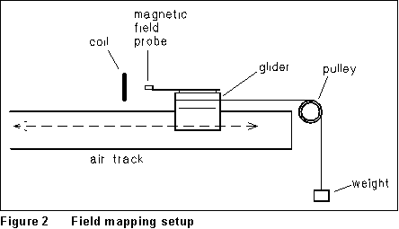 In this experiment,
a tightly-wound circular coil will have a known current passed through
it. A magnetic field probe will pass along the axis of this coil, and magnetic
field data will be taken. The magnetic field probe is attached to an air
cart which is pulled by a weight hung over a pulley (Figure 2). The idea
is to use the shaft encoder (a device which allows one to measure rotations
of the pulley in the form of angle) along with the magnetic field probe
to take magnetic field and angle data as a function of the position of
the probe.
In this experiment,
a tightly-wound circular coil will have a known current passed through
it. A magnetic field probe will pass along the axis of this coil, and magnetic
field data will be taken. The magnetic field probe is attached to an air
cart which is pulled by a weight hung over a pulley (Figure 2). The idea
is to use the shaft encoder (a device which allows one to measure rotations
of the pulley in the form of angle) along with the magnetic field probe
to take magnetic field and angle data as a function of the position of
the probe.
A small weight hung over the pulley will pull the air cart and move
the magnetic field probe into the region of the coil. A sweep will be made
and saved with the plane of the coil vertical, and another sweep will be
made with the plane of the coil horizontal, and the probe passing about
one inch above the coil. In the second case the sweep will permit one to
check the distance scale derived from the angular measurements, and to
review the direction of magnetic field near the loop.
(1) Carefully determine the radius of the pulley on your shaft
encoder. You should be able to do this to within about 1%. Explain the
method which you use to get this precision. Make a careful estimate of
the average diameter of the copper coils. The coil is supposed to be 190
turns of number 22 wire. This AWG 22 enameled wire is listed as 37.0 turns
per linear inch, from which you can get the wire diameter including enamel.
Measure the thickness of the plastic wall surrounding the wires.
(2) The field mapping program is LOGANGLE.EXE in the C:\LAB
directory. Begin by going to Set ANALOG PARAMETERS [item 8] and
select channel B, -10v to +10v scale, and SYNC mode. Then
go to SET ANGLE DATA PARAMETERS [item 7] and select 400 data points,
one channel mode, and set the program to record every 20th point. Later
on, during the experiment, you may want a different number of data points,
or a different number for measuring every Nth point. Now select MORE
ANGLE DATA PARAMETERS [Item 6], and use item 4 in this menu to set
the pulley radius in cm. This sets the apparatus for recording distance
in cm, rather than angle in radians. Skip the calibration; we will convert
it later to appropriate units.
(3) The magnetic field probe is a 'linear Hall effect transducer.'
This is a small, black, approximately rectangular solid with three wires
connected to it. The probe detects a magnetic field component which is
perpendicular to the plane of the small, flat, black detector package.
In our experiments, the plane of the probe is vertical, and the direction
of the magnetic field component which is detected is along the direction
of travel of the air track.
Begin by having the plane of the coil vertical. Adjust the supports
under the coil so that the magnetic field probe passes through the center
of the coil. Connect the coil to the 6 Volt DC supply through an ammeter.
Carefully check the wiring. Turn the supply on. The current should be in
the neighborhood of 1/2 ampere (500 mA). Leave the supply on throughout
the experiment; it is a bad idea to unplug any wires with current flowing,
because the coil has inductance, and sudden disruptions of current create
voltage spikes. In analyzing the data later, you will use the current in
Equation (1) to calculate the magnetic field in the center, so you can
re-graph the data as magnetic field vs. distance.
(4) To make a sweep, set the probe about 30 cm from the center
of the coil, with the air supply turned on, and the thread attached to
a nut hanging over the pulley. First release the air cart, and then just
after the cart has begun to move, press a key to take data. Stop the cart
just as it reaches the end of the track. If the program has not finished
taking data, you will need to move the cart backward until it says that
data taking is complete. When data is complete, plot Z (which is the voltage
from the magnetic field sensor) vs. q. [Item 5; the actual plot is V vs.
distance]. When you have a run with about equal amounts of data on each
side of the maximum, save the data to a file. Note that you may look at
the data on the CRT screen if you wish, by using item 3 on the File I/O
menu. This will show what variables are saved, and how many data points
are saved.
(5) Since you will have to determine the inflection point of
the experimental data, do another run starting about 50 cm from the ring,
and finishing just after recording a maximum in the magnetic field. This
will provide more precision in the position of the inflection point. Save
this data to another file.
(6) Now rest the coil on a horizontal surface, and adjust the
height of its supports until the probe is about an inch above the top of
the coil. Start the probe about 10 cm outside the coil and do a run in
which the probe passes over a diameter of the coil, one inch or so above
the top of the coil. If things are aligned properly, the positive and negative
peaks in the data should be the same size. If this is not the case, try
to readjust and do another run. Save this data to a file when you have
a record of magnetic field from 10 cm outside the coil going over the center
of the coil, and for about 10 cm outside the coil on the other side. Save
this data to another file.
Analysis
(1) Use your three data sets to generate three graphs of magnetic
field vs. distance. To do this, you will have to re-scale the magnetic
field. You can determine the gauss/volts value from the maximum value of
the axial magnetic field (you can calculate what it should be in theory
knowing the coil parameters and the current). Then re-scale the data so
that it is in gauss. (Remember that it will initially SAY it's gauss in
the file, but it's really volts, because we did not calibrate.)
What about the zero of magnetic field? Will you have to make some correction
for this? Look over the graphs, decide what to do, and explain carefully
what you did in your lab notebook.
(3) Determine from the graphs the distance from the center of
the coils to the inflection point in the axial magnetic field. Compare
this to the calculated inflection point from the formula for axial magnetic
field.
(4) From the data where the plane of the coil is horizontal,
locate the positions of maximum positive and negative magnetic field. What
do these represent? Draw a sketch of the magnetic field lines around the
coil to illustrate your discussion of the coil.
Do the maxima and minima have the same absolute values? (That is, is
one the negative of the other?) Based on what you know of the theory of
the magnetic field, should one be the negative of the other? Discuss reasons
why the experimental measurements may not match the theory. Ask yourself
about where the magnetic field is zero, and whether the measured value
is really zero.
From this same graph, determine the diameter of the coils, assigning
some uncertainty to the value. Compare this to the value you obtained directly
with a meter stick or other measuring instrument.
Magnetic Force Between Parallel
Currents
From IFYCSEM 6/96