| Table of Contents |
Crummett and Western Physics: Models and Applications,
Sec. 28.1
Halliday, Resnick, and Walker, Fundamentals of Physics (5th
ed.), Sec. 29-4
Tipler, Physics for Scientists and Engineers (3rd ed.), Sec.
24-4
A current flows in a material because there are free charges moving physically through the material. In a magnetic field, there is a force on the moving charges which results in a difference of electrical potential across the sample. This phenomenon is the Hall effect; in this experiment you will use it to determine the sign and the density of free charges in a semiconductor.
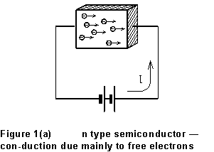
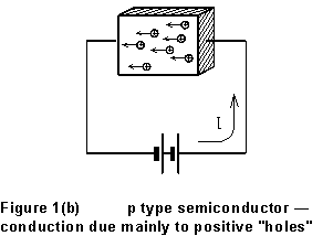
Current in a semiconducting material can be by the transport of either positive or negative charge. If the current is carried mainly by free electrons, the material is "n type"; in a "p type" material, current is primarily due to the motion of positive "holes." A hole is a vacancy in the crystal lattice where an electron is missing from a (bound) site; it acts as if it were a free positive charge. The two cases are contrasted in Fig. 1 below. In each case, the external battery produces an electric field directed from right to left in the material. The holes in the p-type material drift along the field, while the free electrons in the n-type material drift against the field direction.


The current is determined by the number of free charge carriers per unit volume ( ) in the sample material, by the speed (vD) at which they drift along the field, and by the dimensions of the sample. If we have a rectangular sample of width w and thickness t, then
![]() (1)
(1)
where e = 1.602 x 10⁻¹⁹ C is the electron charge. In a magnetic field, there will be a force on each carrier tending to shove it sideways, given by
![]()
As a result, there will be an excess of free charge on one side of the sample, and a deficiency on the other side. The nonuniform distribution of charge will give rise to a difference of potential between one side of the sample and the other. It is not hard to see that this "Hall voltage" is given by
 (2)
(2)
where the width w is transverse both to the current and to the magnetic field direction.
The point of all this is that measurement of VH gives you the drift velocity of the charge carriers, from (2). Moreover, once we know vD, Equation (1) can be used to find the density of charge carriers (n). Finally, the sense of the potential difference gives you the sign of the free charge carriers; this is plain from Figure 2, in which the magnetic field shoves the free charges, whatever their sign, to the left (looking along the current).
One complication, in practice, is that a measured VNM (in Figure 2) will not be
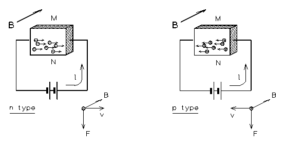
Figure 2 -- Conduction in a semiconductor in an external magnetic field (B)
the same thing as VH. The point is that, even without the magnetic field, points N and M would not be at precisely the same potential, because you can't get the leads connected in precisely the right places. In practice, we have to work around the difference. Suppose that there would be some potential difference V0 between N and M, even when I = 0, due to an IR drop along the current flow. Then with the magnetic field on, we will observe
![]()
where VH is the Hall voltage. Now suppose we reverse the direction of the magnetic field, without changing anything else. This time we measure
![]()
so that, plainly,
 (3)
(3)
and the unknown "offset" voltage V0 has been eliminated.
The discussion above predicts -- compare Equations (1) and (2) -- that the Hall voltage in a given sample will be directly proportional to the current. You will investigate whether or not this is so, determine whether your sample is an n- or a p-type semiconductor, and infer values for its physical properties n and vD.
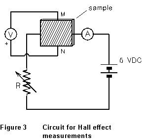 (1) Figure
3 shows a circuit in which the current through the sample is controlled
by variable resistor R. A precision digital multimeter (A), in series
with the sample, measures the current through it; another (V) measures
the potential difference across the sample, VNM.
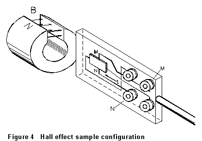
(2) Figure 4 is a sketch of the sample board, slide, and permanent magnet assembly. With the board oriented as shown (the magnet to your left) the magnetic field will be directed away from you. With the sample in the position shown, carefully trace the circuit from the positive (red) terminal of the 6V power supply to be sure that the (conventional) current is flowing from right to left through the sample. If it is not, switch the connections to the current terminals. Also, make sure that point N, on the lower edge of the sample as you view it, connects to the positive terminal of the voltmeter. It's very important to have these connections right, since the sign of the effect is one of the things you're trying to measure!
 (3) A
suggested range of operating currents is indicated on your sample board.
Set variable resistor R so that the current is near the middle of
this range. Record the value of VNM that you read. Now
slide the sample into the center of the region between the poles of the
magnet. Record the value of VNM that you read that you
read now. Did turning on the magnetic field make point N more positive,
or more negative? Based on this observation, what is the sign of the charge
carriers in your sample? (Hint: consider the effect of the
 ![]() force on the charge carriers.) Check your conclusion with the lab instructor
before continuing.
force on the charge carriers.) Check your conclusion with the lab instructor
before continuing.
(4) Now adjust R until the current in the sample is near the low end of the suggested range. Orient the sample as in Fig. 4 and slide it into the magnetic field. Record VNM and I. Remove the sample, rotate it 180 about its axis, and slide it back into the field. Record VNM' and I. If I is not the same for the two trials, take the average of the two values as your value of I for this voltage reading.
(5) Repeat step (4) for each of ten or twelve current settings spanning the range on your sample board. For example, if the recommended range is 10-60 ma, you'd take data in 5 mA increments. In some of the samples, the change of resistivity with temperature may cause your readings to change slowly with time -- especially at higher currents. If this occurs, confine yourself to a lower current range. Be careful that it is the measured potential difference with the sample oriented as in Fig. 4 that you record as VNM each time.
(6) Estimate the width of your sample (transverse to the direction of current flow)and the uncertainty in this measurement. (The uncertainty is going to be relatively big.) Record the sample thickness marked on your board.
(7) Use a gaussmeter to measure the magnetic field between poles of the magnet on your sample board. The instructor will show you how. Try to get the sensitive tip of the gaussmeter probe at the same spot in the magnet that your sample occupied. Try this several times to get an idea of the uncertainty in the field value you measure. Note that the SI unit for magnetic field is the tesla (T): 1 T = 10 kilogauss (kG).
(1) Calculate VH for each of the current values you used in steps (4) and (5) above. Based on the theory, what relationship do you expect between VH and I? Draw a graph of VH vs. I. Is it consistent with your expectation? Find a best overall value of the ratio VH/I and a standard error for it.
(2) Calculate a value (with uncertainty) for the density of free charge carriers in your material.
(3) Determine the drift velocity of electrons or holes in your sample at the largest current value for which you made measurements. Estimate the error in this determination. Will vD be the same at lower current values?
last update 6/96