| Table of Contents |
Crummett and Western, Physics: Models and Applications,
Sec. 11-3
Halliday, Resnick, and Walker, Fundamentals of Physics (5th
ed.), Sec. 11-8
Tipler, Physics for Scientists and Engineers (3rd ed.), Sec.
8-2
Bedford and Fowler, Statics: Engineering Mechanics
Introduction
Terminology: The word 'torque' does not typically appear in the index to statics books such as Bedford and Fowler. For these authors, the same idea is expressed as the 'moment of a force' about a point. Physicists, in turn, never refer to the 'moment of a force', but only to torques. We will attempt to use both terms interchangeably in this discussion.
Background: Torque is the rotational equivalent of force
(a force tends to accelerate a body, while a moment of a force tends to
make a body rotate.) A force, F, applied at point P is said to exert a
torque, ![]() , or to have
a moment, M, with respect to a (reference) point R. For now, we will use
the following definition of the magnitude of the moment M of a force
, or to have
a moment, M, with respect to a (reference) point R. For now, we will use
the following definition of the magnitude of the moment M of a force ![]() applied at point P with respect to point R:
applied at point P with respect to point R:
magnitude of moment (M) or torque (![]() )
)
![]()
where ![]() is a vector
drawn from point R (the reference) to point P (where the force
is a vector
drawn from point R (the reference) to point P (where the force ![]() is applied). The magnitude of
is applied). The magnitude of ![]() is r, and
is r, and ![]() is the
angle between
is the
angle between ![]() and
and
![]() , traveling clockwise.
(Some of you may know that
, traveling clockwise.
(Some of you may know that ![]() is the magnitude of
is the magnitude of ![]() ,
the vector cross product of
,
the vector cross product of ![]() and
and ![]() .)
.)
Rotational Equilibrium: A body in translational equilibrium has no net forces acting on it: the sum of all forces acting equals zero. A body in rotational equilibrium has no net torque acting on it; the sum of all moments of forces on the body equals zero.
General Idea of the Laboratory Exercises: The main purpose is to acquaint you with the features of torque; the way the torque depends on the distance to the reference point, the angle of application of the force, and the fact that any stationary point R can be selected as a reference. (Once this point is selected, all torques in a given situation must be computed with respect to this point.)
![]()
Preliminary Measurements: The measuring bar has holes numbered 1 through 13. Please measure the distance from hole 1 to each of the other holes. Estimate distance to at least the nearest mm, and possibly to the nearest 1/2 mm. ( In the suggested procedure which follows, holes 1,4,5,6,7,9,11, and 13 will be used, so you may be able to get by with measuring just these.) Each station has a mass of 400-500 grams which will be suspended by a hanger during the experiment. Be sure to measure this mass. You will also need the mass of the measuring bar, the curved brass hanger (about 10 gm) and the scale itself (around 47 gm).
 Experiment:
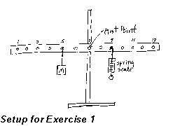
In this exercise you will vary the distance from the pivot point to the
spring scale, measuring the force required to keep the bar horizontal at
each distance. Set up the 'measuring bar' pivoted in the middle (hole 7),
so the bar is free to rotate in a vertical plane. Hang a mass of about
0.4 kg from hole 5, then use one of the spring scales in hole 9, by putting
the curved brass hanger through the hole and attaching the scale to the
brass hanger below the measuring bar. Make sure the scale is zeroed in
a vertical position with nothing pulling on its lower end. Then pull on
the lower end such that the bar is stable in a horizontal position. The
scale reading plus the weight of the scale plus the weight of the brass
hanger will equal the downward force on the bar. Record the value of the
force (N) needed to keep the bar in rotational equilibrium. Repeat this
procedure with the spring scale in holes 11 and 13, recording the force
required (straight down) at each position. Have your lab partner then do
a set of measurements.
Experiment:
In this exercise you will vary the distance from the pivot point to the
spring scale, measuring the force required to keep the bar horizontal at
each distance. Set up the 'measuring bar' pivoted in the middle (hole 7),
so the bar is free to rotate in a vertical plane. Hang a mass of about
0.4 kg from hole 5, then use one of the spring scales in hole 9, by putting
the curved brass hanger through the hole and attaching the scale to the
brass hanger below the measuring bar. Make sure the scale is zeroed in
a vertical position with nothing pulling on its lower end. Then pull on
the lower end such that the bar is stable in a horizontal position. The
scale reading plus the weight of the scale plus the weight of the brass
hanger will equal the downward force on the bar. Record the value of the
force (N) needed to keep the bar in rotational equilibrium. Repeat this
procedure with the spring scale in holes 11 and 13, recording the force
required (straight down) at each position. Have your lab partner then do
a set of measurements.
Analysis: Take the reference point R at the pivot, and compute the moment of the 4 Newton weight (0.4 kg mass). Assign it a 'sense' of CW (if it tends to make the bar rotate in the clockwise sense) or CCW (if it tends to make the bar rotate in the counter-clockwise sense). Now compute the torque of the spring scale (with respect to the pivot) when at each hole. Use the average of the forces measured by each partner. Propagate the errors in each of the torque values. Is the sum of the moments equal to zero in each case within your estimated uncertainty?
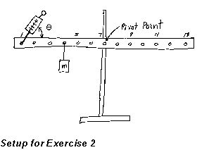 Experiment:
In this exercise you will vary the angle the spring scale makes with the
measuring bar and measure the force required to keep the bar horizontal
for each angle. Keep the bar pivoted at hole 7, hang the 4 Newton weight
from hole 4, and attach the spring scale to hole 1 from above via its curved
hook through the string attached to hole 1. Make sure the scale is zeroed
in the vertical position with no force on its lower end. Let the force
be exerted at angles of 30, 45, 60, and 90 degrees to the length of the
bar (the bar should stay horizontal). Record the forces at each angle,
and have your partner do a set of readings too. Compute the torques at
each angle. Also compute the moment of the suspended 4-N weight. Do the
torques at various angles remain constant within your estimated experimental
uncertainty?
Experiment:
In this exercise you will vary the angle the spring scale makes with the
measuring bar and measure the force required to keep the bar horizontal
for each angle. Keep the bar pivoted at hole 7, hang the 4 Newton weight
from hole 4, and attach the spring scale to hole 1 from above via its curved
hook through the string attached to hole 1. Make sure the scale is zeroed
in the vertical position with no force on its lower end. Let the force
be exerted at angles of 30, 45, 60, and 90 degrees to the length of the
bar (the bar should stay horizontal). Record the forces at each angle,
and have your partner do a set of readings too. Compute the torques at
each angle. Also compute the moment of the suspended 4-N weight. Do the
torques at various angles remain constant within your estimated experimental
uncertainty?
What do you conclude from these two exercises? Include your conclusions in the lab write-up, and discuss briefly with the lab instructor before going on to the next part.
Experiment: In this exercise you will measure the moment of the 'measuring bar' due to its own weight with the pivot point at hole 13? Does this torque depend on the angle of the measuring bar with respect to the horizontal? Devise a way to use the spring balance to determine the moment of the measuring bar with respect to the outer hole when the bar is horizontal. Carry out the measurement, trying to obtain results which are fairly precise.
Analysis: Calculate the torque of the bar when horizontal with respect to the outer hole. Does the mass of the measuring bar play a role in the moment? Measure the mass of the bar, and try to come up with a formula which would give the same moment as the one you calculated from the force measurements. Discuss your results with the lab instructor before going on.
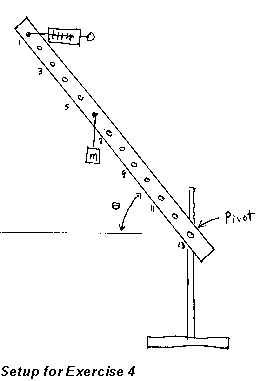 Experiment:
In this exercise you will investigate a case where the measuring bar is
not horizontal. Pivot the bar at hole 13, suspend the 4-N weight from hole
6, and attach the spring scale via the string at hole 1. (Make sure the
scale is zeroed for reading in a horizontal position.) With the bar at
about 45 degrees above the horizontal, have the spring pull in a horizontal
direction toward the pivot at hole 13. Move the bar slowly to some convenient
angle (don't try for any specific angle like 45 degrees). Notice that the
horizontal force on the spring scale for rotational equilibrium varies
as the angle of the measuring bar varies. Read the force on the spring
scale, and carefully measure horizontal and/or vertical distances which
will let you determine the angle of the measuring bar to the horizontal.
Do two trials. Sketch this setup, and record all important information
(distances, scale readings, etc.).
Experiment:
In this exercise you will investigate a case where the measuring bar is
not horizontal. Pivot the bar at hole 13, suspend the 4-N weight from hole
6, and attach the spring scale via the string at hole 1. (Make sure the
scale is zeroed for reading in a horizontal position.) With the bar at
about 45 degrees above the horizontal, have the spring pull in a horizontal
direction toward the pivot at hole 13. Move the bar slowly to some convenient
angle (don't try for any specific angle like 45 degrees). Notice that the
horizontal force on the spring scale for rotational equilibrium varies
as the angle of the measuring bar varies. Read the force on the spring
scale, and carefully measure horizontal and/or vertical distances which
will let you determine the angle of the measuring bar to the horizontal.
Do two trials. Sketch this setup, and record all important information
(distances, scale readings, etc.).
Analysis: Use the pivot as the reference point R, and compute the torques about this point, taking the CCW torques to be positive, and the CW torques to be negative. Does the sum of the moments about R equal zero within your estimated experimental uncertainty? (Don't forget that there is a torque from the mass of the measuring bar.)
Analysis: In this exercise you will revisit the data you took in exercise 1 and change the reference point about which the torques are calculated. There is no experimental portion to this exercise. Use the data from exercise 1, but use a reference point R' which is the outer hole on the bar when it is stationary in a horizontal position. When the reference is the outer hole on the bar, you will have to compute the torque from the net force at the pivot (hole 7). This force acts upward, and is the sum of the two downward applied forces. Calculate the net moment about R' for any two of the positions where you did measurements. Does this net moment approximately equal zero, as it should for rotational equilibrium?
Chapter 4 -- Electricity and Magnetism -- Some General Remarks
last update 7/97