 The basic relation
between electrical quantities is Ohm's law. If the (DC) potential
difference across a circuit element is
 | Table of Contents |
Many of you reading this are in your first physics laboratory. Even if it isn't your first, it's probably the first electrical laboratory that you've taken. Before you start, let me summarize some elementary points about dealing with electric circuits, which may or may not be familiar to you.
First, as to safety: All these experiments run off 6V or 12V power supplies. Voltages in this range might jolt you, but won't do any damage. Most items of equipment, however, are more fragile than you are; and it's always a good idea to have the lab instructor check your circuit before applying power to it.
 The basic relation
between electrical quantities is Ohm's law. If the (DC) potential
difference across a circuit element is
 ![]() V,
and the current flowing in it is I, then
V,
and the current flowing in it is I, then
![]()
where R is called the resistance of the circuit element.
 Diagrams of electric
circuits are usually schematic, not pictorial, because uaually the schematic
conveys all the information we care about (and it leaves out a lot that
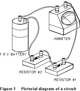
we don`t need to care about!). Figure 1 shows a very simple circuit, two
resistors and a battery all in series, with a meter to read the current.
In a schematic diagram, the same circuit would look as in Figure 2. The symbols are standard: a pair of clearly unequal plates represents the battery, a zigzag line the resistance. A simple labelstands for the meter. Straight lines in a circuit diagram represent connecting wires, but pure connection, no resistance. (If the resistance of the physical connecting wire were significant we would include it as a separate resistor in the schematic.) You should start getting used to such schematic diagrams.
Two circuit elements can be connected together in either of two basic ways, illustrated below. If they are connected so that any current must flow first through one and then through the other, they are said to be in series. Resistances in series simply add. If the two resistances are connected so that each element is connected across the same two points A and B, they are in parallel.

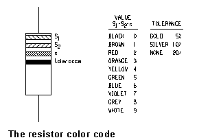
 Commercial resistors
are usually marked with colored bands indicating their value. The numerical
color code is shown in the diagram at the right. The first three bands
give the resistance value as two significant digits S1S2
followed by n zeroes. (Thus, for instance, red-red-brown means "2,
2, followed by one zero," that is, 220
 ![]() .)
.)
Proper analysis of DC circuits usually requires that you keep track of the signs of various quantities. The center terminal of a dry cell is usually positive. One trick that will help you keep track is to use red leads for the higher-voltage side of a circuit, and black leads for the return to the negative side. More often than not, it's the negative side of a circuit (if either) that is connected to ground.
 Coaxial cables
consist of a center conductor, surrounded by insulation, which is surrounded
in turn by a braided conducting "shield" or outer conductor,
then finally by insulation again. The shield connects to the outer shell
of the cable connector, which usually connects to the chassis of an instrument,
or to ground; the connector has a center pin which connects to the center
wire of the cable. When pigtails have been spliced onto a coax cable, you
can usually tell which terminal connects to the outer shell (it's usually
black) and which to the center wire.
Analogue meters (the old-fashioned pointer-against-a-scale kind) sometimes have mirrors to help you line up your eye; if so, use them. In any case, the accuracy of this kind of meter is seldom better than 5% of the full-scale value, and often no better than 10%. Thus, if you read 6.2 volts on a 10 V scale, it's probably not better than 6.2 ± 0.5 V. (The reproducibility of several readings is a different question; it may well be better than this.) Digital meters are no more precise than one or two units in the last decimal place that is showing, and in some cases, if the value you are reading is fluctuating, may be less precise than this. Their absolute accuracy depends on how long it has been since they were calibrated; check with your instructor.
Always observe the current limits on decade resistance substitution boxes. Also notice that many of these boxes have a third "ground" lug which just connects to the case. This is not connected to the box's resistance and you will generally not want to use it.
Circuits containing capacitance and resistance have the characteristic property that the potential difference across the capacitance cannot change faster than about
![]()
Note that RC is, indeed, a time:
(farad)(ohm) = (C/V)(V/A) = (C/A) = sec
last update 7/96