EM11 MAGNETIC FIELD IN A SOLENOID HALL EFFECT PROBE
OBJECTIVES
To become familiar with the use of the Hall-Effect Device
for measuring magnetic fields; to verify the relationship between the current
in the windings of a solenoid and the magnetic field it produces at the
center of the solenoid; to explore the variation of the magnetic field
within the solenoid core as a function of distance inside the core for
a constant solenoid windings current.
To observe the effect that different materials in the
solenoid core have on the magnetic field values.
PROBLEM ASSIGNMENTS
1. An air-core solenoid 25 cm long has 1500 turns. The
windings of the solenoid carry a current of 1.15 Amp. Compute the magnetic
field at the center of the solenoid core. Assume that the formula for an
infinitely long solenoid applies. Answer: B = 8.7 x 10⁻³ Tesla
2. The transverse voltage (VH) developed across a Hall-Effect
Device is proportional to the external B field to which it is exposed.
A calibration chart states that VH = KB. The value of K is given as: K
= 9.7 Compute the following:
- i) the "K" value in the units? Answer: 0.97
- ii) the B field when the VH value is 120 mV. Answer:
B = 1.2 x 10⁻² Tesla
3. Review the Hall-Effect phenomenon and identify conditions
under which the Hall-Voltage is not likely to be linearly related to the
magnetic field B.
Answer: Changing of drift velocity and/or the number of
charge carriers/m3.
4. How many turns are required for an air-core solenoid
approximately 50 cm long so as to produce a magnetic field of 55 gauss
at the center when a current of 650 mA is flowing in the windings?
Answer: 3367 turns
APPARATUS
- 2 Fluke digital multi meters (One meter must have a "relative"
measurement selection feature)
- 1 Hall Effect Device mounted on a Probe (HED-P)
- 1 Anatek Power Supply, connecting wires with banana leads
(assorted sizes)
- 1 Solenoid.
- 1 Cylinder of each of the following materials in labeled
cardboard boxes:
- 1 Strong small magnet (cow magnet) 1 4" long nail
PROCEDURE
- Caution:
- i) Do not exceed 2 Amp in the solenoid windings.
- ii) The HED-P is to be handled with care. It should not
be plugged directly into the power supply.
Part A: Magnetic field produced at the center of the solenoid
by applied current to the solenoid.
- a. Connect the two sets of Anatek DC output terminals
in parallel so as to access the maximum possible current of 2 Amps from
this parallel combination. Connect the power supply in series with the
solenoid and one of the multi meters as an ammeter (see Figure 1). Select
the 2000 mA (2 Amp) range on the ammeter.

Figure 1
- b. Turn the current control knobs on the power supply
to zero setting. Turn the voltage control knobs to the maximum possible
setting (clockwise rotation). Turn the power supply on. Use the current
control knobs to establish various current flows in the solenoid.
Hall Effect Device Probe (HED-P)
- c. Connect the AC adapter of HED-P to the bench outlet.
Use the second digital meter as a voltmeter and connect the output leads
from the HED-P to the voltmeter as sketched in Figure 2 below. Record the
HED-Probe number on the probe. Find and record the sensitivity (K) value
and its units for your probe. (Look up this probe number on the lab equipment
calibration display board, located near the entrance.) Also record the
total number of turns (N) stated on the solenoid and measure its inside
length (L). Record these values in space provided on page 4.
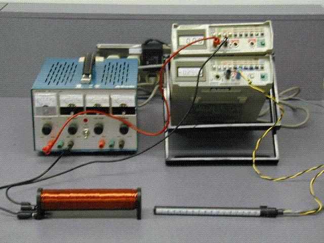
Figure 2
- d. Turn the voltmeter on. You will notice that there
is a DC reading of around 1.5 to 2.5 volts. Switch on the voltmeters Relative
Measurement function by pressing the Relative ON button on the voltmeter.
The voltmeter will now read zero volts.
- e. Establish a current of about 750 mA in the solenoid.
Insert the HED-P into the core of the solenoid. Locate the region of the
core over which the maximum possible reading of VH is obtained. Estimate
the center of this region. Keep the probe in this region for the duration
of Part A of the experiment.
- f. Reduce the current to zero. Check the probe output
reading. It should be zero volts, which suggests zero B field in the coil.
If necessary reset the Relative ON button on the voltmeter.
- g. Starting from zero current, vary the current in the
solenoid in increments of 200 mA up to a maximum of 1800 mA. Note the VH
reading on the HED-P corresponding to each value of the solenoid current.
- h. Record your data as suggested in Table 1.
Part B: Variation of B field within the solenoid for a
fixed current in its windings.
- i. In this part of the experiment, select a current of
about 950 mA. Your task is to explore how the value of B varies from one
open end of the solenoid to the other.
- j. Remove the sensor from the core. Check that the probe
Hall voltage reads zero (VH = 0) when the HED-P is away from magnetic field.
If not, reset the relative button on the meter .
- k. Place the probe at the open end of the core (opposite
to the end with the terminals). Call this location as x = 0. With the current
value set as in (i) above, note the VH value at x = 0.
- l. Insert the probe in increments of 1.5 cm in the core
until the probe has traversed the entire length of the core. For each location
"x" in the core, note the corresponding VH value. Record the
values of position versus VH in Table 2. Also record the maximum value
of VH in air in Table 3.
Part C: The effect of different materials in the solenoid
core on the B field produced by a fixed current in the windings.
- m. Switch off the current to the solenoid. Insert the
aluminum cylinder into the core so that the cylinder is close to the center
of the solenoid core.
- n. Establish the same current in the windings as you
did in Part B.
- o. Insert the probe into the core and observe the maximum
possible value of VH on the voltmeter. Switch the current off.
- p. Replace the Aluminum Cylinder by a Copper Cylinder
and repeat steps (m) and (n) above.
- q. Replace the copper cylinder by a steel one and repeat
the steps (m) and (n) above.
- r. Tabulate your data as suggested in Table 3.
- s. Insert a common nail partially into the core. Switch
on the current. Observe what happens to the nail. Reverse the nail ends.
Repeat by switching the current on. Note the effect on the nail.
- t. Repeat step (s) by inserting the magnet. Treatment
of Data
Part A: Current in the windings of the solenoid and the
resulting B field at its center. HED-Probe # Probe Sensitivity, K = Volts/Tesla
, # of turns in coil, N = Length of Coil, L = ___________
Table #1: B field in the center of the solenoid as a function
of varying currents in the windings.
Obs. Current (I) (mA) Sensor Voltage (VH) ( Volts ) B
( Tesla ) 1 0.0 2 200 3 400 4 600 5 800 6 1000 7 1200 8 1400 9 1600 10
1800
Sample calculation of B field for Table #1 and Table #2:
Given VH = KB ; B = = (Record result below)
For current = , K = , B =
- a. Use the curve-fit analysis to determine whether a
linear relationship exists between B and I.
- b. Refer to equation 2 (in the theory section) and the
results of the curve-fit analysis to calculate the Number of turns N on
the solenoid that you used. Compare (% difference) this experimental value
of N to the given value of N that you recorded above Table #1. (See Procedure
Part A,c.)
Part B: Variation of B field within the core of the solenoid
for a fixed current in the windings.
Table #2: Variation of B field with an air core solenoid
as a function of location
- a.Calculate the B field at each location using the same
equation in Part A. (You may use Gauss or Tesla for this calculation)
Steady Current =
Location X ( cm ) VH ( Volts ) B ( Gauss ) 0 1.5 3.0 4.5
6.0 7.5 9.0 10.5 12.0 13.5 15.0
- b. Use the curve fit program to print out a graph showing
the variation of B as a function of the sensor location within the core.
Naturally, you will use the "free-form" analysis.
Part C: Effect of different materials in the solenoid
core on the B field produced by a steady winding current.
Table #3: Bmax in the core in the presence of different
materials.
Current in the solenoid = .
Material VH (max) B (max) Air Aluminum Copper Steel
Observations arising from steps r and s in Part C.
Report : For this lab you are required to write a conclusion/discussion
section for your results in the usual format with the following points
in mind. (Do not forget to show any relevant calculations or data analysis
in its own section)
Part A
- a. What does the slope of the B versus I (relating to
data in Table #1) represent?
- b. From your analysis of the data in Table #1 state the
calculated Number of turns on the solenoid used in the lab. (See equation
#2 in Theory section) State the % difference between the given value of
the Number of Turns of the solenoid and this experimentally calculated
value.
- c. Do your results above support the theoretical relationship
between B and I as given by equation #2? (Is the percent difference within
allowable (approximate) errors in the experiment to say that the equation
#2 has been verified?) How would you estimate the allowable errors for
this part of the experiment.
Part B
- c. Comment on the variation of B within the core of the
solenoid for the fixed current used in this part.
- d. Estimate the maximum and minimum values for the rate
of change of the B field as a function of its location.
Part C
- e. Compare the results of VH and B, for each material
inserted into the core, with those found with nothing (air) inserted into
the coil. Explain why some materials inserted in the coil increase the
magnetic field and others do not.
- f. Explain the behaviors of the common nail and the magnet
when placed at the entrance of the solenoid core?
Appendix 1
B FIELD IN A SOLENOID
THEORY
Refer to your textbook for the following topics: B field
at the center of a circular current carrying conductor and/or the B field
of a solenoid. You will find that the B field at the center of an infinitely
long solenoid (which essentially means high ratio of length of solenoid
in relation to its diameter) is given by:
B = µo(n)I = µo(N/ )I (1)
where µo = mag. permeability of free space = 4 x
10-7
n = turns per meter (m-1);
=length of coil (m)
N = total turns in length of coil = (n) x ( )
I = Current (Amp)
B = magnetic field in Tesla
(Recall that 1 Tesla = 10,000 Gauss.)
If the solenoid is not infinitely long, then the B field
at the center is smaller than that given in Equation 1. For the "finite"
solenoid you are using in this lab, the correction factor is calculated
to be 0.98. This means that the field at the center of your lab solenoid
is 98% of the value it will have if it was an infinitely long solenoid.
The Equation 1 for the solenoid you are using becomes:
= (0.98) µo(n) Where = slope of Graph #1(2)
NOTE: Do not confuse the slope constant "B"
with the magnetic field symbol B
The output voltage (VH = KB) (3)
Where K = conversion factor, the value of K will be supplied
to you in the lab. This value of K may vary with the HED-P used
B =
Where B – magnetic field (T) Vout – output voltage of
Hall effect sensor (V) VoQ – output voltage of Hall effect sensor when
B = 0 (V) Sens – sensitivity of sensor is different for each device and
will be supplied by your instructor Appendix 1