Entries
Perry A. Tompkins
Physics Department Samford University
800 Lakeshore Dr. Birmingham, Al 35229
Phone 205.726.4121 Fax 205.726.2329
patompki@Samford.edu
AND
Low-Cost Entry
Three Lamps in Parallel and Series
Abstract
A very common circuit problem in introductory physics involves three lamps in a simple circuit. Students generally can predict the behavior of the circuit when the three lamps are in parallel, but have no clear understanding of their behavior when the same lamps are placed in series. This apparatus allows the exploration of these circuit concepts.
Support required for apparatus:
Approximate size Base :1foot by 6 in, 2 feet tall
Does this apparatus require Electrical Power? yes
Will you be present to set up your apparatus? yes
Other support needed for the proper operation of this apparatus: none
Three Lamps in Parallel and Series
Abstract (same as abstract above)
A very common circuit problem in introductory physics involves three lamps in a simple circuit[1]. Students generally can predict the behavior of the circuit when the three lamps are in parallel, but have no clear understanding of their behavior when the same lamps are placed in series. This apparatus incorporates three everyday light bulbs on lamp sockets and a series of knife switches which can allow setting these bulbs up in either series or parallel. This apparatus is used as a conclusion to simple resistance circuit theory before entering branching circuits.
Theory
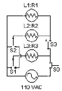
Three lamps in a simple circuit can be treated as three fixed resistors in the circuit and a simple solution can be determined using established addition of resistors in series and parallel. Figure 1 shows a circuit that includes knife switches that allow configuration of the three lamps into both parallel and series circuits.
Figure 1. Three lamps in the circuit(L1, L2, L3) can be configured to be in parallel and series using the switches (S1, S2, S3).
The circuit shows an AC source. Even if AC theory has not been covered, the following description is accurate by using the rms voltage in the calculation, thereby suppressing the AC nature of the circuit. The switch S0 is a safety cutoff if the apparatus cover is opened and does not play a part in the physics of the circuit. The three lamps L1, L2, and L3 will be treated as three resistors R1, R2 and R3.
When the three switches are all switched to the outside, the circuit is completely parallel. In this situation the voltage across all three lamps is the line voltage. All three lamps show normal brightness. For this demonstration L1 = 60 W, L2 = 40 W and L3 = 25 W were used. Combining Watt’s law and Ohm’s law will allow the determination of the resistance and current of each lamp. A summary of the equations for voltage, current, resistance and power is given in Table 1. The numerical values are not very accurate due to the change in resistance when a lamps heat, and are not included.
Table 1. Summary of calculations for the circuit in Figure 1, in both the Parallel and Series configurations.
| Element | Voltage | Current | Resistance | Power |
| Parallel | ||||
| L1 | V | V/R1 | R1=V2/P1 | P1 |
| L2 | V | V/R2 | R2=V2/P2 | P2 |
| L3 | V | V/R3 | R3=V2/P3 | P3 |
| Series | ||||
| L1 | I*R1 | V/(Rtot) | R1 | I2*R1 |
| L2 | I*R2 | V/(Rtot) | R2 | I2*R2 |
| L3 | I*R3 | V/(Rtot) | R3 | I2*R3 |
When the three switches are all switched to the inside, the circuit is completely series. At this point all the three lamps must have the same current. The voltage is "shared" among the lamps to make the total voltage drop add up to the line voltage. Ignoring the temperature dependence of the resistance of each lamp, a simple application of Watt’s and Ohm’s laws will show that the lamp with the lowest wattage rating will receive the largest portion of the voltage, and therefore will be brightest. A summary of the equations for voltage, current, resistance and power is given in Table 1. For the wattage listed above, L1 will get 20.4% of the voltage, L2 will get 30.6% and L3 will get 49%. These ratios will vary for different wattage lamps but are not dependent on the line voltage. The voltage in L1 is not high enough to make it light. This tends to be counterintuitive for most students, but is easily calculated and demonstrated.
Materials list
The materials needed for construction are listed in Table 2.
Table 2. Materials needed including costs.
| Item | Amount | Description | Cost |
| 1 | 1 | 12"x 24" x ½" piece of wood | 2.94 |
| 2 | 3 | Flush mount light bases | 7.38 |
| 3 | 1 | Extension Cord | 0.97 |
| 4 | 3 | SPDT knife switches | 7.17 |
| 5 | 1 | Terminal connector | 1.00 |
| 6 | 2 | Hinges | 4.26 |
| 7 | pkg | Terminal lugs | 1.40 |
| 8 | 3 ft | Black and Red wire | 5.00 |
| 9 | 3 ft | Aluminum angle iron | 3.35 |
| 5 ft2 | Thin Plexiglas | 7.11 | |
| misc | Hardware | 2.00 | |
| 1 | Kill Switch | 3.94 | |
| Total Cost | $46.52 |
All materials are available at mega-hardware stores such as Lowe’s or Home Depot except items number 4 & 5. Item 4 is available from Central Scientific Company and 5 from Newark Electronics. Nothing on the list is critical and substitutions can be easily made. The author suggests that the knife switches and visible wiring and terminals be used to allow complete visualization of the circuit.
Construction and Set-up
The constructed apparatus is shown in Figure 2. In the figure the knife switches are set to form the Series circuit. The 25 W is the brightest, the 40 Watt is very dim and the 60 W does not seem to be lit. If the knife switches were reversed, the circuit would be in Parallel, and the lamps would show their normal brightness, with the 60 W being the brightest and the 25 W being the dimmest.
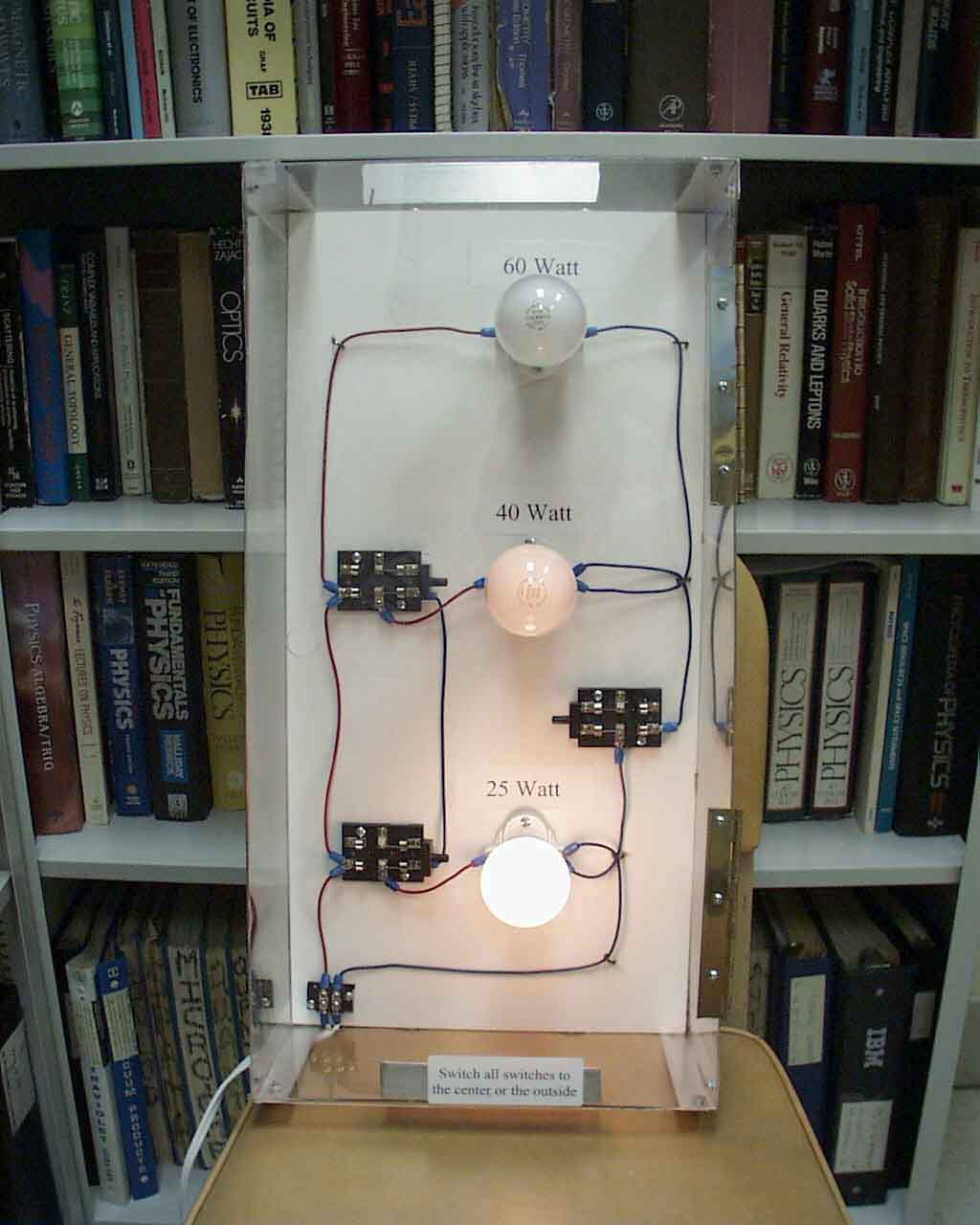
Figure 2. Apparatus for three lamps set in Series.
The construction is open, as long the circuit diagram in Figure 1 is followed. It was attempted to key the wire colors to maximize the difference between the series and parallel circuit, but this was not very successful, due to the dual use of some wires and single use of others. As stated above, the wire connections and knife switches are exposed to allow viewing of the various current paths available to the circuit. For safety, a high current kill switch is mounted in one of the cover hinges. The main AC power runs through this switch. If the lid is raised the power is cut off. Due to the simplicity of the circuit, this apparatus is not sensitive to current surges or miss-set knife switches.
Execution
We generally complete the parallel calculation in class before using the apparatus. After the currents and voltages are determined, the students are requested to set the system up in the parallel configuration, and to show that everything goes as expected. Next the students are requested to predict the behavior of the circuit in series. They set up the circuit and test to see the outcome. Many students predict behavior inconsistent with actual performance. After a simple circuit analysis, the actual performance is easily understood.
Conclusions
This apparatus is useful in concluding the concepts of simple parallel and series circuit analysis. Its simplicity and use of everyday components seem to be appreciated by students. The actual wattage used by the lamps in the series configuration are numerically different from the calculations due to the variance of resistance with temperature in a normal incandescent lamp, but the qualitative nature is very illustrative. Additionally, discussions about the temperature dependence can be used to compare and contrast the idealization of theory and the real behavior of circuit elements. Other lamp combinations are possible, but 60:40:25 seems to allow the clearest delineation of brightness in the series mode.
References
[1] Serway and Faughn, College Physics, Fifth Edition, Saunders College Publishing, 1999.