Bill Franklin
3339 Chimney Place Drive Waco, TX 76708
254-754-3903
physicsnerd@yahoo.com
AND
Low-Cost
Fan Cart With Sails for Forward, Reverse, and No Motion
Abstract
The device shows that a fan blowing into a sail on the same cart (or boat) can propel itself forward, backward or not at all, depending upon the shape of the sail. The effect stirred some controversy in TPT in 1986.
Support required for apparatus (i.e. special needs in order to set up the equipment at the AAPT meeting): At least 1.5 m of table space.
Approximate size: 25 cm high, 25 cm long, 20 cm wide. It runs on a track about 1.3 m long.
Does this apparatus require Electrical Power? No.
Will you be present to set up your apparatus? Yes.
Other support needed for the proper operation of this apparatus: none
You must submit a complete description of the apparatus with this entry. The description should be suitable for publication in a professional journal and be detailed enough that others can duplicate the apparatus. This description (anonymous) will be available to the judges of the apparatus. on following pages
Detailed Discussion
The idea of propelling a boat by directing a fan at its sail has been around longer than I have. It is one of those “cartoon physics” ideas that’s funny because it contradicts your experience. Robert Beck Clark tells about a test question based on it that he encountered in the early 1960’s, and the confusion generated when one student responded--with a good argument--that it was possible. (See The Physics Teacher January, 1986, pages 38-39.)
The student argued that air bouncing off the sail would undergo a larger momentum change than it gained from the fan. If its velocity could be reversed by the sail without loss of speed relative to the boat, then the momentum change would be double that supplied by the fan to speed the air up from rest. Even if you account for air initially moving relative to the fan and for speed loss upon reversal by the sail, you might still have an imbalance capable of propelling the boat. The student in the story received credit, although he contradicted the expected answer.
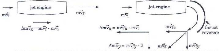
In his article, Clark refers to the thrust reversers on some jet aircraft that work much like the fan and sail in the problem. Air is sped up relative to the plane by the jet engines, then turned around by clam-shell thrust reversers. The momentum change at the reverser is greater than that in the engine, giving a net momentum change for the air opposite that normally provided by the engine. The result is that the plane is slowed, rather than being driven forward. The air is also deflected downward, which makes it push up on the plane, as required by Newton’s third law. This provides additional lift, which is useful at low landing speeds. The sketch on the left below shows the normal operation of the engine; that on the right shows the reverse thrust mode.
An older example is the Pelton water wheel. In that device, a jet of water was directed into curved blades to reverse the water’s direction and nearly double the force exerted on the blade, compared to letting a flat blade stop the water. More exquisitely designed blades are used today to squeeze as much thrust as possible from the steam or exhaust gases in steam or gas turbines.
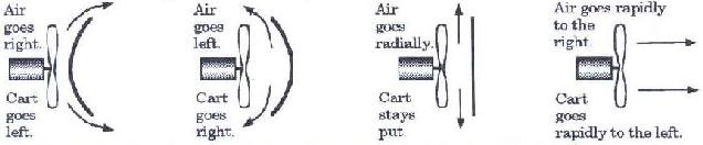
The fan-sail effects can be effectively demonstrated with a fan cart. Make your own using low-friction wheels or an air track glider. Or buy one from any of several vendors. They can be used to show how the air stream from the fan can be deflected by a sail to produce forward or backward motion, or, with a flat sail perpendicular to the air stream, no motion at all. Actually, the greatest effect is obtained by removing the sail entirely! In that case, the impulse acting to speed the air is accompanied by an equal impulse acting on the fan (Newton’s third law again), without being partially canceled by an impulse on the sail.
All four cases are sketched below, where the arrows are a rough indication of the air flow. The carts are omitted for clarity, but in each sketch, the fan and the sail must be attached to the same cart.
Complete construction plans for a device to demonstrate the behavior of fan driven sails follow. It consists of an inexpensive DC motor and a sail made of a plastic plate mounted on a base. The base is made to fit a Pasco dynamics cart. If you do not have one, low friction wheels, such as Pasco’s ME-9492 (four wheels on two axles for $16) can be attached to the base with one screw per axle. This allows the wheels to be easily removed to be used elsewhere. The other parts cost less than $5. Adding the sails to an existing fan cart reduces the cost only about $1.
Construction:
Check off each step as you complete it.
1. Make the smaller plastic plate into a shallow dish by cutting off the outer rim, leaving no lip. Also make the larger plastic plate into a flat disk by cutting just inside the first bend. The resulting “sails” will both be about 7 3/4” in diameter. See the sketches at the right.
2. Cut two of the craft sticks in half, making four 3” sticks. Use hot melt glue to attach two of the 3” sticks and one 6” stick to one of the pipes, as shown at the left. Repeat with the the other pipe and the remaining craft sticks. This makes two masts for the sails.
3. Lay the flat disk on the table. Run a bead of hot glue on the craft sticks of one mast, and quickly press the hot glue against the disk, centering the craft stick cross on the disk. In the same way, attach the other mast to the convex side of the shallow dish. See the sketch at the right.
4. Drill the shaft hole of the propeller out to 5/64” and press the propeller onto the motor shaft. Attach the motor to the mount with the cable tie, as shown at the left. Run a bead of hot glue along each side of the motor to keep it from sliding.
5. Hot glue the motor mount into the 1/2” hole in the base, as shown at the right. Insert the CPVC coupling into the 13/16” hole. Drill a 3/32” hole in the end of the base and clear through the coupling. Tap the nail into this hole to lock the coupling in place.
6. Cut the connector off of the battery holder wires, if there is a connector. Cut off half of the red wire. Strip the ends of both wires. If there is double- sided foam tape on the battery holder, use it to attach the holder to the base. If not, use hot glue.
 7.
Solder the black lead from the battery holder to the negative terminal
(-) of the motor. Solder the alligator clip lead to the positive terminal
(+) of the motor. Connecting the alligator clip to the stripped end of
the red wire turns the fan on. (Or you can attach a switch to the mount
and replace the alligator clip lead with a short wire.)
7.
Solder the black lead from the battery holder to the negative terminal
(-) of the motor. Solder the alligator clip lead to the positive terminal
(+) of the motor. Connecting the alligator clip to the stripped end of
the red wire turns the fan on. (Or you can attach a switch to the mount
and replace the alligator clip lead with a short wire.)
8. Now insert one of the masts into the coupling. Place
the base into the tray of a Pasco dynamics cart, and place the cart near
the center of a carefully leveled track.. Then add AA cells, turn on the
fan and see what happens. Small lengths of Christmas tree tinsel or other
small streamers can be taped to the edges of the sails to make the direction
of the air stream visible. The three sail configurations are shown below
(without the carts). The fourth possibility is to have no sail at all,
as in steps 5 & 6.
9. If you don’t have a Pasco cart and track, you can keep costs to a minimum by cutting shallow grooves in the bottom of the base to hold the axles of low friction wheels, such as the Pasco ME-9492 (four wheels on two axles for $16). The axles can be attached with one short screw per axle. This makes them easily removable to use elsewhere. See the sketch at the right, which is a bottom view of the base.
or Lecture Demonstration
AND
Low-Cost
Rotating Sail Magnus Effect Demonstrator
Abstract
The device allows a controlled study of the existence and direction of the force on a rotating object in an air stream, such as a curving baseball. It is a small scale model of Anton Flettner's rotating sail ships of the 1920's.
Support required for apparatus (i.e. special needs in order to set up the equipment at the AAPT meeting): At least 1.5 m of table space. An electrical outlet.
Approximate size: 45 cm high, 25 cm long, 10 cm wide. It runs on a track about 1.3 m long.
Does this apparatus require Electrical Power? Yes, for a small fan.
Is this apparatus intended for use with an overhead projector? No.
Will you be present to set up your apparatus? Yes.
Equipment required to construct apparatus:
Saw, hammer, screw driver, drill and several bits, soldering iron, wire cutters.
Item Source/Store Part Number Cost Total cost. See page 4. Cost of materials is about $4, plus wheels ($16 if needed), and a fan (perhaps $5 at a garage sale).
Sketch (computer generated if possible) See page 3
Description
It is simply a 2-liter bottle rotated by a small DC motor about a vertical axis and supported on low-friction wheels. With wind from the side provided by a fan, it is driven forward or backward. Reversing the spin, reverses the force.
Detailed Discussion
Demonstrating Why Spinning Balls Curve
In the planning stages of a workshop for physics teachers on the physics of sports, one of our leaders offered to share his expertise on giving volleyballs spins that make them curve. That started me thinking of a way to demonstrate the effect so that the attendees could easily see how it worked. Better still, could I devise something easily constructed and inexpensive enough that they could each build one and take it back to show their students?
What came to mind was a ship I remembered seeing a picture of once that had rotating cylindrical sails. A light-weight cylinder is easy to come by; two-liter soft drink bottles can be fished out of almost any trash can. In short order I had a prototype, and it worked! I later learned that Pasco makes such a device, but not many public schools could afford its price to illustrate a non-essential topic like this. My device is designed to fit on a Pasco dynamics cart (as is Pasco’s). Low friction wheels are necessary, because the force is small. A school without low friction carts could keep cost to a minimum by using a set of low friction wheels, such as Pasco’s ME-9492 (four wheels on two axles for $16). Held in shallow grooves by single screws, the axles can be removed and used elsewhere. The other parts cost less than five dollars.
The device consists of a two-liter bottle mounted with its axis vertical in a wood and PVC pipe framework. It is spun by an inexpensive DC motor. My first model had a DPDT switch to reverse the direction of rotation. This reversal is essential; students need to see that the cart movement reverses when the rotation does. The construction is simplified and the cost reduced by making connections with alligator clip leads. Besides, it is more obvious to the class that you are reversing the connections to reverse the rotation. To my mind, that makes it a more effective demonstration, if a bit less convenient.
The wind for this sail is provided by an electric fan. The fan should be kept directed at the center of the bottle. If the air flow were directed mostly to one side of the bottle, the Bernoulli effect would push the bottle into the air stream, like a ping-pong ball entrapped by the stream of air from a vacuum cleaner.
The sketch at the right approximates the air flow around the rotating sail. The surface drag slows the air on one side (the bottom side in the sketch) and speeds it on the other (top) side. It also drags the air flowing past the top beyond the midpoint, while retarding the air flowing past the bottom. The result is that the air flowing near the rotating sail is deflected somewhat downward. Recognizing this, you can explain the forces in any of several ways.
The easiest, especially if fluids have not been studied yet, is to appeal to Newton’s laws. Since air is deflected downward, the sail must be exerting a downward force on it (Newton’s second law). Then by Newton’s third law, the air must be exerting an upward force on the sail. Or note that the air gains a downward momentum, which requires a downward impulse. Then it must exert an upward impulse on the sail.
A third explanation is in terms of the Bernoulli principle, which is basically a conservation of energy statement. It says that pressure and speed are inversely related along a streamline in a flowing fluid. Consider the streamline that divides to flow around the two sides of the cylinder. In this case, the flow is slower at the bottom, so the pressure should be higher there. The pressure difference between bottom and top then provides the force that pushes the sail upward in the sketch.
Since viscous drag is important, as well as differences in air speed, the effect is not fully described by the Bernoulli equation. It was explained by Heinrich Magnus in 1851, and is called the Magnus effect.
There are yet other ways of dealing with the phenomenon, in terms of circulation or vortices, but these are more abstract, and are more popular with engineers than with high school students.
I was able to locate the picture at the right of the ship that inspired this device, a 1920’s attempt to sail a ship with such rotating cylinders. The idea didn’t catch on, but it did work. Anton Flettner built two ships with rotating sails and crossed the Atlantic with them. The first , in 1922, was an old sailing ship. The second, in 1927, was a cargo ship with a 1000 hp diesel engine that drove the ship at 9 knots with an underwater screw propeller. Using rotors alone, it achieved 6 knots. Using both propeller and rotors raised the speed to 13 knots in a good wind.1
Of course, the device also models the behavior of a spinning ball moving through air. It was to explain the curving of spinning balls in such sports as baseball, volleyball, tennis, golf, and ping-pong, after all, that the device was invented. It has several advantages over demonstrations with thrown balls. For one, it stays in approximately the same place, while the air flows past it, rather than whizzing across the room. It is also obvious from anywhere in the room which way it is being pushed. With a thrown ball, this can only be seen by someone pretty much along the path of the ball. Finally, the definite axis makes the spin direction very obvious, which is not usually the case for a thrown ball.
It proved to be easy to build and a hit with those who attended the workshop. Complete instructions follow.
While searching for a picture of Flettner’s ship, I found an excellent resource for the Magnus effect, as well as many other topics related to lift and flight. It is a soon to be published book, See How It Flies, (ISBN 7016405) by John Denker. It will be available from McGraw Hill for about $35. It is currently available on the internet at: http://www.monmouth.com/~jsd/fly/how/htm/title.html#mytoc. This is the address for the main menu; chapters can be accessed from there.
I recently found an article by Thomas Greenslade, Jr. in the January, 1971 issue of The Physics Teacher, in which he describes a similar device, also inspired by Flettner's ships.
1 Douglas Lobey, Ships Through the Ages (Octopus Books, Ltd., 1972), p. 115-117.
Construction:
1. Drill a 3/16” hole about 1” from each end of the short wood block (cart socket). Place it near the center of the bottom (unmarked) side of the bottom block. Attach it with two 1-1/4” drywall screws through the holes in the cart socket, as shown at the right.
2. Drill 3/16” holes in the center of each 1/2” PVC end cap. Use the nail and a hammer to make starter holes at the marks near each end of the top and bottom boards. Attach an end cap at each starter hole using four 1/2” #8 screws, as shown at the left.
3. Press the two PVC pipes gently into the end caps to tentatively connect the top and bottom boards into one unit, as shown at the right.
4. Cut the alligator clip lead into two equal parts, and strip 3/8” of insulation from each of the cut ends. Slip one stripped end through the hole in one motor terminal and wrap it around the terminal, making a good mechanical connection. Repeat with the other wire and motor terminal. Solder both connections, heating the terminal from one side and touching the solder to the other side. Do not touch the solder directly to the soldering iron.
5. Run the wires along the side of the motor to the shaft end. Being careful to avoid shorting the wires to the metal motor parts, press the motor (terminal end first) into the 1” hole, as shown at the right.
6. Drill a 3/16” hole in the center of the bottom of the 2 liter bottle and a 1/16” hole in the center of the cap. Screw the cap firmly onto the bottle. Slip the cap on to the motor shaft. Push the nail through the hole in the top board and into the hole in the bottom of the bottle. Press the top and bottom boards together firmly, but not so tightly that the bottle rubs on the top board. The bottle should spin freely.
7. Attach the battery holder to the bottom block and add a AA cell (one fresh cell is enough), with the flat end of the cell in contact with the spring of the holder. Place the apparatus on a low friction cart. The cart socket is made to fit a Pasco dynamics cart. Connect the wires to the battery holder. The motor should spin the bottle. Aim a fan at the apparatus from the side. The cart should move either forward or backward. Reverse the battery connection to reverse the spin direction. This should also reverse the direction that the cart moves.
8. If you don’t have a Pasco cart and track, you can keep costs to a minimum by cutting shallow grooves in the bottom of the cart socket to hold the axles of low friction wheels, such as the Pasco ME-9492 (four wheels on two axles for $16). The axles can be attached with one short screw per axle. This makes them easily removable to use elsewhere. See the sketch at the right.
AND
Low-Cost
Cheapskate Elastic/Inelastic Collision Demonstrator
Abstract
The device shows that inelastic collisions are due to some mechanism for transforming the center of mass kinetic energy of the colliding object into some sort of internal energy. In this case, energy is transferred to sloshing water.
Support required for apparatus (i.e. special needs in order to set up the equipment at the AAPT meeting): At least 1 m of table space.
Approximate size: 15 cm high, 30 cm long, 10 cm wide. It needs room to roll into a 'wall' consisting of a board clamped to the table.
Does this apparatus require Electrical Power? No.
Is this apparatus intended for use with an overhead projector? No.
Will you be present to set up your apparatus? Yes.
Equipment required to construct apparatus:
Screw driver, drill and several bits, sheet metal shears, scissors.
Item Source/Store Part Number Cost Total cost. See page 3. Cost of materials is about $2
Sketch (computer generated if possible) See page 2
Description of apparatus
It consists of a plastic soft drink bottle, partially filled with water, taped to a cheap plastic skate with a steel loop spring on one end. The spring end is rolled into a rigid wall. If all of the air is squeezed out of the bottle, the skate rebounds elastically. If air is admitted, the water can slosh around and there is very little rebound.
Detailed Discussion
In totally elastic collisions the colliding objects leave with the same total kinetic energy that they brought to the collision. But in many collisions, kinetic energy is lost. Why are some collisions elastic and others inelastic?
Total energy is always conserved. If kinetic energy decreases, what increases? Usually it is internal (or thermal) energy, the kinetic and potential energies of the molecules that make up the colliding objects. Unlike the center of mass kinetic energy of an object, internal energy is invisible. Moreover, it is difficult to detect.
Consider a 1.5 kg cart, traveling at 2 m/s, and making a completely inelastic collision by deforming a 40 g lead strip. The total kinetic energy is 1.5 J, enough to raise the temperature of the lead by about 0.3 K. That can be detected by a sensitive probe. In fact, I’ve had students do it as a lab, but I’m not convinced that it was worth the time and effort. It can be replaced by a quick, easy, and highly visible demonstration.
An article by Uri Ganiel appeared in The Physics Teacher in January, 1992, describing an apparatus that could be used for the purpose. It consisted of 24 machined brass weights hung by rubber bands from a frame attached to a low-friction cart equipped with a springy bumper. When the cart collided with a rigid wall, the weights oscillated about in analogy to the molecular motions within an object heated by an inelastic collision.
To make it clear that this was the mechanism responsible for the low elasticity of the collision, Ganiel built a second frame on which similar weights were threaded on vertical rods to keep them from oscillating. With this frame on the cart, the collision was much more elastic.
I was impressed by the idea, but needed a cheaper and more easily built apparatus for physics teachers to make at workshops. My version had a light wooden frame mounted on a cheap plastic skate with a spring of steel band mounted on one end. Two 3 ounce disk-shaped fishing weights (total mass about 180 g) hung from the frame by rubber bands. Because the total mass of the skate and frame was less than 300 g, these two weights were adequate to absorb most of the kinetic energy of the collision. Also, they were easily unhooked from nails in the frame and dropped into a piece of PVC pipe, where they couldn’t move about.
I started with the weights in their pipe nest, and demonstrated that the collision was highly elastic. Then I hung the rubber bands on the nails, and showed that the collision became inelastic. It was immediately clear to students that the center of mass motion was lost to the internal motion of the suspended weights. From there, it was an easy connection to thermal energy.
If internal motion were not possible, all collisions would be perfectly elastic. In fact, most collisions between atoms are perfectly elastic. The exceptions are collisions that are energetic enough to raise one or more electrons to higher energy states within the atoms (or eject them entirely), and collisions in which the atoms stick together.
Recently, while searching old issues of The Physics Teacher, I came across an article by John Stull in the April, 1969 issue. Stull presented a similar idea. He taped a test tube to a spring-equipped air track glider. When the tube was empty or completely filled with water, the glider would make highly elastic collisions. When it was partially filled, the sloshing water provided a mechanism for absorbing much of the energy.
This inspired a modification of my previous apparatus. I replaced the wood frame and weights with a plastic soda bottle taped to the skate. The bottle is filled about 2/3 full with water, all of the air is squeezed out, and the cap is tightened. With no sloshing possible, the cart collides quite elastically. Then the cap is loosened, the bottle is allowed to resume its original shape, and the cap is retightened. This time, the water sloshes and the cart hardly bounces at all. The effect is slightly enhanced by stuffing some plastic screen into the bottle to provide quicker damping of the water’s motion, but this is not essential.
This apparatus is really an intermediate step between the oscillating weights and molecular motions. You might choose to do the demonstration with the weights and follow it using the water, in order to make the transition to thermal energy a more gradual one. However, either one will do, and the water version is easier to build and cheaper (less than $2).
 The
cheap plastic skates prove to be ideal for this demonstration, because
the wheels have a modest amount of friction. I tried mounting the apparatus
on a very low-friction cart and found that it was less convincing. The
problem is that, even though the skate rebounds very slowly when internal
motion is allowed, if the wheels have very little friction, the cart still
rolls back to you. With a little friction, it doesn’t go far. Because students
tend to focus on whether it returns, rather than how quickly, the contrast
is much less apparent to them if it does.
The
cheap plastic skates prove to be ideal for this demonstration, because
the wheels have a modest amount of friction. I tried mounting the apparatus
on a very low-friction cart and found that it was less convincing. The
problem is that, even though the skate rebounds very slowly when internal
motion is allowed, if the wheels have very little friction, the cart still
rolls back to you. With a little friction, it doesn’t go far. Because students
tend to focus on whether it returns, rather than how quickly, the contrast
is much less apparent to them if it does.
Construction:
Inexpensive plastic “beginner’s skates” can be found at dollar stores. I like the Larami brand, 071802125833, but others will do. (See diagrams )
1. Remove the straps and adjust the skate length to maximum. Drill a 3/16” hole about 1/2” from the bottom center of the outside surface of the heel stop. If the heel stop is double walled (like the Larami), Don’t drill through the inner wall.
2. Make a spring by drilling a 3/16” hole about 3/8” from each end of a 9” length of steel strap. The strap is used to bind pallets of lumber, and can be obtained free from a lumber yard. Bend the spring into a circle so that the two holes line up fairly well.
3. Put a #8 x 3/8” pan head machine screw through the holes in the spring and into the hole in the heel stop. Place a nut on the end of the screw and tighten it to secure the spring to the skate.
4. Place a plastic soft drink or water bottle with a cap (1/2 or 1 liter, 16 or 20 oz. size) on the skate with its bottom end against the heel stop. Use about a foot of duct tape to attach it around the “waist” of the skate.
The effect is slightly enhanced by stuffing some plastic screening in the bottle. This is not essential, but here’s how to do it:
5. beginning with a 6” square of screening, make the four cuts shown.
 6.
Roll and hot glue both ends into cones by gluing the edges labeled “a”
to each other and by gluing the edges labeled “b” to each other. Then hot
glue the triangular scraps to the waist between the cones to give the assembly
more rigidity.
6.
Roll and hot glue both ends into cones by gluing the edges labeled “a”
to each other and by gluing the edges labeled “b” to each other. Then hot
glue the triangular scraps to the waist between the cones to give the assembly
more rigidity.
7. Roll the shape up, one end at a time, to squeeze it into the bottle. It will relax back into its double-cone shape. Water sloshing back and forth in the bottle, will have to pass through the mesh. The turbulence created will speed the transformation of the motion into random thermal motion of water molecules.