|


| |
Please
note:
- Install the
TSCC codec in order to view
the "Professor Solution" video clips.
- Select the "28k" link if you are off campus using a modem, otherwise
select the "128k" for better audio quality.
- You need a soundcard in order to hear the audio discussion.
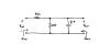
- Click on the circuit thumbnail image to see the full size version.
- Click and drag cursor over the "Answers" cell to reveal the answer,
or click the answer icon
 . For best results, work the problem
yourself, then reveal the answer. . For best results, work the problem
yourself, then reveal the answer.
- Recently added examples are indicated by the
 icon. icon.
Equivalent resistance
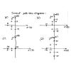
| Circuit |
Schematic |
Problem Statement |
Professor Solution |
Answer |
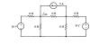
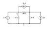
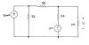
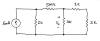
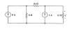
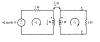
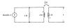
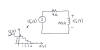
| equiv 1 |
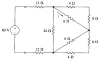 |
Find the equivalent resistance seen by the
60-volt source. |
28k /
128k |
30 ohms |
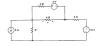
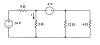
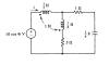
| equiv 2 |
 |
Find the equivalent resistance seen by the
50-volt source. |
28k /
128k |
10
ohms |
Node voltage analysis
| Circuit |
Schematic |
Problem Statement |
Professor Solution |
Answer |
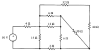
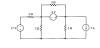
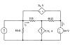
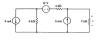
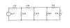
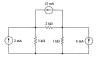
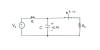
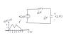
| nodal 1 |
 |
Find the currents i1
and i2 using the node
voltage method. |
28k /
128k |
2A, 4A |
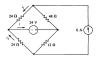
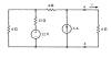
| nodal 2 |
 |
Find the current i using the node
voltage method. |
28k /
128k |
1.5A |
| nodal 3 |
 |
Find the current i using the node
voltage method. |
28k /
128k |
4 A |
| nodal 4 |
 |
Find the power delivered by the 17-volt
source and the 2-amp source using the node voltage method. |
28k /
128k |
51
W, 4 W |
| nodal 5 |
 |
Find the current i and the voltage
v using the node
voltage method. |
28k /
128k |
1
A, 6 V |
| nodal 6 |
 |
Find all node voltages using nodal analysis. |
28k /
128k |
30
V, -8 V,
7 V, -20 V |
| nodal 7 |
 |
Find all node voltages using nodal analysis. |
28k /
128k |
40
V, -280 V |
| nodal 8 |
 |
Find the currents i1 and
i2 using the node
voltage method. |
28k /
128k |
8
A, -4 A |
| nodal 9 |
 |
Find I and V using nodal
analysis. |
28k /
128k |
-2
A, -8 V |
| nodal 10 |
 |
Find the gain of the circuit using nodal
analysis. |
28k /
128k |
-0.5 |
Superposition
| Circuit |
Schematic |
Problem Statement |
Professor Solution |
Answer |
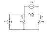
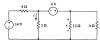
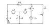
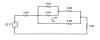
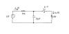
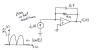
| super 1 |
 |
Find the voltage V. |
28k /
128k |
6.67 volts |
super 2
|
 |
Find the voltage V. |
28k /
128k |
8
volts |
super 3
|
 |
Find the voltage V when R is 2
ohms |
28k /
128k |
8
volts |
super 4
|
 |
Find i using superposition. Hint: Find
the currents i1 and i2
first. |
28k /
128k |
3
amps |
Proportionality
| Circuit |
Schematic |
Problem Statement |
Professor Solution |
Answer |
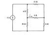
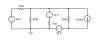
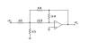
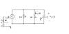
| prop 1 |
 |
Find the voltage Vo. |
28k /
128k |
3.75 volts |
| prop 2 |
 |
Find the current i using the
proportionality method. |
28k /
128k |
714
mA |
| prop 3 |
 |
Find the voltage v using the
proportionality method. |
28k /
128k |
8 V |
| prop 4 |
 |
Find the current I using the
proportionality method. |
28k /
128k |
313
uA |
Source transformations
| Circuit |
Schematic |
Problem Statement |
Professor Solution |
Answer |
source 1
|
 |
Find the voltage V
using repeated source transformations. |
28k /
128k |
48
volts |
source 2
|
 |
Find the power associated with the 6-mA
source using repeated source transformations. |
28k /
128k |
-12
mW |
source 3
|
 |
Find i using source transformations. |
28k /
128k |
1 A |
Thevenin / Norton equivalents
| Circuit |
Schematic |
Problem Statement |
Professor Solution |
Answer |
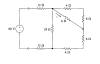
thev 1
|
 |
Find the Thevenin equivalent circuit as seen
to the left of terminals a-b, then find the current i. |
28k /
128k |
28
V, 8 ohms
2
amps |
thev 2
|
 |
Find the Thevenin equivalent circuit as seen
by the 4-ohm resistor, then find v. |
28k /
128k |
6
V, 8 ohms
2 V |
thev 3
|
 |
Find the Norton equivalent as seen by the
4-ohm resistor, then find i. |
28k /
128k |
17.5 V, 10 ohm
1.25 A |
Mutual inductance
| Circuit |
Schematic |
Problem Statement |
Professor Solution |
Answer |
mutual 1
|
 |
Find the AC steady-state currents i1
and i2. |
28k /
128k |
15sin(8t-37deg) A,
3sin(8t) A |
mutual 2
|
 |
Find the AC steady-state current i(t). |
28k /
128k |
3.29cos(4t+9.5deg) amps |
mutual 3
|
 |
Find the AC steady-state voltage v(t). |
28k /
128k |
3.88cos(4t-166deg) volts |
s-domain analysis
For each of the problems in this section: Transform the circuit to the s-domain,
use circuit analysis to solve for the desired result in the s-domain, then use
the inverse Laplace transform to obtain the time-domain result.
| Circuit |
Schematic |
Problem Statement |
Professor Solution |
Answer |
s-domain 1
|
 |
Find the equation for vC(t)
that is valid for all time t, and sketch a graph of the equation. |
28k /
128k |
|
s-domain 2
|
 |
Find equations for i1(t) and
i2(t) that are valid for all time t, and sketch a graph of the equation. |
28k /
128k |
|
s-domain 3
|
 |
Find the equation for vC(t)
that is valid for all time t, and sketch a graph of the equation. |
28k /
128k |
|
s-domain 4
|
 |
Find the equation for vo(t)
that is valid for all time t, and sketch a graph of the equation for t = 0
to 8 seconds. |
28k /
128k |
|
s-domain 5
|
 |
Plot vo(t)
for time t = 0 to 10 seconds. |
28k /
128k |
|
s-domain 6
|
 |
Plot vo(t)
for time t = 0 to 15 seconds. |
28k /
128k |
|
Driving point impedance
For each of the problems in this section: Express all results as a
ratio of polynomials in s, using a unit coefficient for the highest order
denominator term.
| Circuit |
Schematic |
Problem Statement |
Professor Solution |
Answer |
imped 1
|
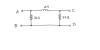 |
Find the driving point impedance Z(s) at terminals
A-B, C-D, and A-C. Comment on any
patterns you see in your results. |
28k /
128k |
|
imped 2
|
 |
Find the driving point impedance Z(s) at terminals
A-B, C-D, A-C, and B-D.
Comment on any patterns you see in your results. |
28k /
128k |
|
Transfer function of a circuit
For each of the problems in this section: Express all results as a
ratio of polynomials in s, using a unit coefficient for the highest order
denominator term.
| Circuit |
Schematic |
Problem Statement |
Professor Solution |
Answer |
transfer 1
|
 |
Find the transfer function H(s) for for terminals
A-B as input and terminals C-D as output. |
28k /
128k |
|
transfer 2
|
 |
Find the transfer function H(s) for for terminals
C-D as input and terminals A-B as output. |
28k / 128k |
|
transfer 3
|
 |
Find the transfer function H(s) using the
proportionality method. |
28k /
128k |
|
Pole-zero diagrams
| Circuit |
Schematic |
Problem Statement |
Professor Solution |
Answer |
pzd 1
|
 |
Draw the pole-zero diagram
of F(s). |
28k /
128k |
|
pzd 2
|
 |
Draw the pole-zero diagram of F(s) given the
time-domain form f(t). |
28k / 128k |
|
pzd 3
|
 |
Find the pole-zero diagram for each transfer
function. |
28k / 128k |
|
pzd 4
|
 |
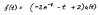
Find the pole-zero diagrams for:
H(s) = Vout(s) / Vin(s),
Zin(s), and Zout(s). |
28k / 128k |
|
pzd 5
|
 |
For each pole-zero diagram, find
H(s) expressed as a ratio of two polynomials in s, with the highest order
denominator coefficient as unity; find H(s) expressed as a sum of basic
terms (do partial fraction expansion) |
28k / 128k |
|
Transfer function realization
| Circuit |
Schematic |
Problem Statement |
Professor Solution |
Answer |
tfr 1
|
 |
Find four different circuits to realize H(s)
as follows:
 |
Passive network: resistor(s) and inductor(s) |
|
Active network: resistor(s) and inductor(s) |
|
Passive network: resistor(s) and capacitor(s) |
|
Active network: resistor(s) and capacitors(s) |
Use "reasonable" component values.
Verify your finished circuits by evaluating their responses
at H(0) (DC) and H(¥) (high frequency). |
28k / 128k |
There are several possible circuit topologies, and the component values are
not unique. |
tfr 2
|
 |
Design a circuit based on resistor(s),
capacitor(s), and op amp(s) that realizes H(s). Use
"reasonable" component values.
Verify your finished circuits by evaluating their responses
at H(0) (DC) and H(¥) (high frequency). |
28k / 128k |
There are several possible circuit topologies, and the component values are
not unique. |
s-plane and AC steady state
Bode plots
|


