In-Class Exercise: Introduction to MIPS and SPIM
Install PCSPIM:
- Download pcspim.zip to your local hard disk.
- Unzip the file. Recommendation: unzip it into a new folder.
- Run the SETUP.EXE program. Recommendation: Accept the default
destination directory.
- Make sure that there is a trap.handler file in the directory into which
you installed PCSPIM (probably C:\Program Files\PCSPIM).
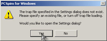
- Run PCSPIM. Expect to get this dialog box, and click "Yes":
- In the "Settings" dialog box that opens next, click "Browse", navigate
your way to the directory in which PCSPIM is installed, and select the
trap.handler file.
PCSPIM is now installed and running. You should see four panes, which
will probably be in this order:
- The first pane shows the contents of the registers. We will be
primarily interested in the general registers.
- The next pane shows the contents of the "text segment," i.e. the program.
It looks messy, but there are just four items on each line, each of which
relate to the same machine instruction. The first item is the address.
The 0x prefix designates a hexadecimal number. The second item is the
hexadecimal representation of the machine instruction. The third item is
(basically) the assembly language representation of the machine instruction.
The fourth item (if it's present) is the actual line from the source file that
generated the machine instruction. Notice that it contains instructions
even though you haven't loaded a program yet. That's the code that
handles any errors in your program, for one thing.
- The third pane shows the data segment, including the stack contents.
For now, we'll only be concerned with the first part (labeled "DATA").
- The last pane shows messages.
There is actually another pane called the console, which opens as its own
window. That's where the input and output for your programs appears.
Load and simulate the first sample program:
These instructions include specific addresses. If they don't match what
you see on your computer, there is probably a problem with the settings for your
trap handler that you should correct before continuing.
- Look at the "text segment" pane (the one that shows instructions).
Notice that the program starts at address 0x00400000 and continues to address
0x0040001c, then skips to address 0x80000080 where the kernel starts.
The code that starts at 0x00400000 handles command line arguments, calls your
program as a procedure, and then exits. Your program will be loaded
immediately after that code, at address 0x00400020. Also notice that the
PC (program counter) register has the value 0.
- Download p03-1.asm to your local hard disk
(Recommendation: right-click on the link and choose Save As).
Open it in your favorite text editor and examine it.
- Open it in PCSPIM (Note: if you get an error, you probably lost the
carriage return at the end of the last line in the process of downloading the
file). Notice that the text segment now includes your
program starting at address 0x00400020. Also notice that the value of
the PC changes to 00400000.
- Set a breakpoint at address 0x00400020 (the Breakpoints command is on the
Simulator menu). Notice that the instruction at that address appears to
be replaced by "break $1." It's not really.
- Start the simulation of your program (the Go command is also on the
Simulator menu). The default starting address of 0x00400000 is correct.
- The simulation should run until it gets to the breakpoint that you set and
then prompt you whether or not to continue. Choose "No." The break
$1 "instruction" will be highlighted.
- Notice the value of the PC.
- Notice that registers $0 and $t2 currently contains zero.
- Single step the program (from the Simulator menu). Notice that the
instruction that was originally at 0x00400020 (ori $t2, $0, 40) appears in the
messages pane, indicating that it has just been executed. Also notice
that the contents of register $t2 have changed, and that the new value is
shown in hexadecimal form. Finally, notice the value of the PC.
- Predict the effects of executing the next three instructions (the second
ori, the add, and the third ori). Which registers will change, and what
will the new values be? Simulate the execution of the instructions.
Did you predict correctly?
- The next instruction attempts to change the value of register $0 to 40,
and when you simulate it, it will appear to have that effect. When you
simulate the next instruction, though, you will see that the value of register
$0 is changed back to 0 before it is used, so in effect it never really
changed. This SPIM behavior is somewhat unfortunate, because it obscures
the fact that register $0 always contains 0.
- The next instruction is the syscall. If you single step one time,
the syscall instruction will remain highlighted, but the PC will change to 0,
indicating that the program has "exited."
- If you single step again, the first instruction in the kernel will be
highlighted, because you just tried to execute an instruction at a bad
address.
- Choose Continue on the Simulator menu. The console should fill with
exception messages complaining about your attempt to execute instructions at
bad addresses. Press Control-C to stop the simulation.
Load and simulate the second sample program:
- Execute the Reinitialize command on the Simulator menu. The register
and text segment contents will return to the state prior to your loading the
first program (note: SPIM occasionally gets confused to the point that
you have to close it and reopen it).
- Download p03-2.asm to your local hard disk, look
at it in your text editor, and then open it in SPIM.
- Set a breakpoint at the beginning of your program, and run the simulation
to the breakpoint.
- In turn, predict the effects of executing the first three instructions
(the first ori, the lui, and the second ori). Simulate their execution.
Did you predict correctly?
- The next instruction in the source file is the first li. Notice that
it actually translates into two instructions. The reason is that the
immediate cannot be represented in 16 bits. This will become more clear
when we talk more about the machine language representations of the
instructions).
- Predict the effects of each of the two instructions and simulate their
execution. Notice that the combined effect is the one intended by the
assembly language programmer, except that the contents of register $1 changed.
By convention, that register is reserved for the assemblers use.
- The next instruction in the source file is the second li. Notice
that it actually translates into a single instruction, because the immediate
can be represented in 16 bits.
Load and simulate the third sample program:
- Reinitialize SPIM, download p03-3.asm to your
local hard disk, look at it in your text editor, open it in SPIM, and run the
simulation to the beginning of the program.
- Notice that the data segment has changed. The array A is stored
starting at address 0x10010000. Notice that each element of the array
requires 32 bits, i.e. 4 bytes, of storage, and that SPIM lists four words per
line, so every 16th address is displayed. The array has 16 elements, and
the variable h is stored immediately following the array, so it is at address
0x10010040.
- The first instruction in the source file is an la, which expands to lui
and ori. Predict its effects and simulate it. Do the new contents
of register $t1 match the assembly language programmer's intent?
- Do the same for the remaining instructions in the program.
Writing your own program:
Modify the third program to find the sum of the last three elements of the
array A and store the result in a new memory variable called total.
Remember that the array is zero-based and that each element requires four bytes
of storage.