Due to the nature of this project and the design document used we have thus far been using the event-oriented and outside-in design methodologies. These design methods seem to fit the project best based on the clients and programmers needs and the requirements document provided. Due to the lack of a conceptual design needed for the client the design document is to be primarily utilized by the programming team. The event-oriented decomposition fits well in this situation because the page formats have been well defined by the client so the main design task is to spell out how certain events change the state of these pages. This also allows work to be started on the general (high level) states while requirements gathers information needed for a more detailed design , whereas modular decomposition may not. Outside-in design is similar to event-oriented decomposition in that it allows the design team to work with the inputs and outputs to the system without immediately considering the specifics of what the system does with this data
<Some designs may require research into what has been done in the past and what is current practice. Also, some designs may need to incorporate past or current work. Learning about what already exists enables you to build upon the work of others, rather than reinventing the wheel. You can get your work done faster and probably do it a little better. Also, if you are trying to build a better system than what is currently available, you can demonstrate that effectively by showing how it improves over past or current work.
You should summarize the past and current, similar and supporting work in YOUR OWN WORDS that pertains to your project. Your summary should include a critical analysis as to the advantages and disadvantages of the work. Your summary serves to focus the past or current work on the project work.
References that you use to show past or current work should be cited here and listed in the Reference Materials Section.>
<Each component in this section must have a unique ID to support cross-referencing. You will want to refer back to the appropriate ID's in this section from the detailed design.>
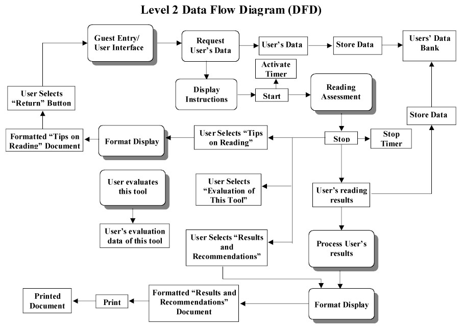
<The diagram in this section should show all user interfaces (screens and reports) and how they relate to each other. The relationship shown would be parent-child. If that relationship is not possible, an "order of display on the screen" relationship may be used. Other types of relationships should be done with instructor permission.
The diagram should only show the user interface names framed in boxes, the user interface names should match those given below, and the lines or arrows connecting the boxes.>
In this section, all the information related to this tool has to be filled in.
In this section, all the information related to this tool has to be filled in.
In this section, all the information related to this tool has to be filled in.
In this section, all the information related to this tool has to be filled in.
In this section, all the information related to this tool has to be filled in.
In this section, all the information related to this tool has to be -filled in.
In this section, all the information related to this tool has to be filled in.
All the instructions for the Reading Assessment goes here. I think this should be provided by the client.
All the instructions for the Reading Assessment goes here. I think this should be provided by the client.
All the instructions for the Reading Assessment goes here. I think this should be provided by the client.
All the instructions for the Reading Assessment goes here. I think this should be provided by the client.
All the instructions for the Reading Assessment goes here. I think this should be provided by the client.
All the instructions for the Reading Assessment goes here. I think this should be provided by the client.
All the instructions for the Reading Assessment goes here. I think this should be provided by the client.
All the instructions for the Reading Assessment goes here. I think this should be provided by the client.
| Mission
The mission of this tool is to provide assessment of reading and feedback on appropriate action to improve academic success. |
Menu | ||||
| # | Question goes here ........? | |
|
|
||
| The reading passage goes here in this area.
When this page loads, only the "Start" button is visible. Only after clicking on the "Start" button do the passage and the "Stop" button appear. At this stage it is better to hide the "Start" button so that the user doesn't accidentally clicks on it.
|
||
|
|
||
| Tip Number 1 | ||
| Tip Number 2 | ||
| ...... | ||
| ..... | ||
| ..... | ||
| ..... | ||
|
|
|
|
|||
| 1 | Time Score | ||
| 2 | Recall Score | % | |
| 3 | Efficiency for Time Use | ||
| 4 | Efficiency for Reading Recall | ||
| Recommendations | |||
|
|
|||
|
|
|||
|
|
|||
| Error Occurred
while processing your request !
Suggestion: |
||
| Error Occurred
while processing your request !
Suggestion: |
||
| Error Occurred
while processing your request !
Suggestion: |
||
<The screen/menu design is shown here, not the actual screen in the program.>
<Bulleted list of component descriptions including format of inputs and outputs.>
- Error: User clicks on "Reading Assessment" at the Main Screen (<ID.ID>) before filling out the guest entry form of Guest Entry Screen (<ID.ID>).
Error Handling: User is prompted with the Error Display Screen (<ID.ID>)
- Error: User clicks on "Results and Recommendations" at the Main Screen (<ID.ID>) before completing the test on "Reading Assessment" Screen (<ID.ID>)
Error Handling: User is prompted with the Error Display Screen (<ID.ID>)
- Error: User clicks on "Evaluation of This Tool" at the Main Screen (<ID.ID>) before completing the test on "Reading Assessment" Screen (<ID.ID>)
Error Handling: User is prompted with the Error Display Screen (<ID.ID>)
<The report design is shown here, not the actual report in the program.>
<Bulleted list of component descriptions including format of outputs.>
<...>
The user will use a monitor (as an output device) to read the choices and to know what he/she has to choose from. The user will also use a mouse (as an input device) to click on various choices on the "guest entry" screen. If the user did not have access to a mouse, he/she could use a keyboard to "tab" to the various selections and use the spacebar or arrow keys to select the desired choice. The system will have error handling in case the user attempts an action that should not be done. The user will not need to type any text. However, the user will need to use drop-down boxes, option buttons, and command buttons.
<If data structures, files, or databases are to be used, then describe them here.
The information in this section should not be repeated in other sections, but you may cross-reference back to it, such as from the detailed design.
Entity relationship diagrams from the requirements document should be converted into the data structures, files, or databases that will actually contain the data. All sizes, formats, and estimated/actual data quantity should be given.
The format below must be used with the <ID> field to support cross-referencing.
<...>
<...>
<...>
>
<This section details the external systems and their interfaces that will be used with the system designed in this document. Examples of external systems are database or other servers, COM objects, other programs (even dll's that are specifically written or purchased for the application) commercial-off-the-shelf systems, other programs, credit card systems, and the like.
The information in this section should not be repeated in other sections, but you may cross-reference back to it, such as from the detailed design.
The format below must be used with the <ID> field to support cross-referencing.
<Describe in detail the purpose of the external system, why it is to be used, and what the external system will provide to the software system designed in this document.
Organize the subsections below that describe the actual interface to the external system by function.
Describe in detail how the interface is to be used from the software system to connect to the external system. Show function names, types, and parameters if applicable or whatever is used to connect to the external system. In all cases, expected input and output should be given along with time delays or problems that could occur and what to do about them.
If the external system has a specific language by which it communicates, be sure to document where its language description can be found (the reference should be given in the references section and cited here). If the language is small, such as 20 or fewer commands, then it may be detailed here.
<...>
>
<This section of the Design Document is organized by the subsystems given in the System Architecture Section. It addresses all levels of abstraction of the system.
The design modeling notation that you use should be with instructor permission.
All algorithms, units, modules, subsystems, classes, etc., are specified in detail. How the software interacts with external systems will be given here. If data structures, files, or databases are used, it will be given here how the software interacts with the them. How the software interacts with the user interaction components is also given.
Special attention should be given to issues, such as performance, error handling, fault tolerance, failure recovery, efficiency, and the like.
It does not repeat the material of other sections in the document, but instead cross-references to them.
All components in the detailed design must have an ID to support cross-referencing. >
<A diagram of the components of this subsystem must be given and how they relate to each other.>
<A detailed description of the component must be made with the instructor approved modeling notation. This may include showing control and data flow, communication with other components, and other portions of the instructor approved modeling notation.
At any level of the detailed design, if a subsystem is broken into other subsystems or component parts, make a diagram of those subsystems or component parts and how they relate to each other. Then go into the detailed design of those subsystems or components.
If a component communicates or interacts with a medium to large number of other components, then a diagram should be shown of how that interaction occurs.>
<...>
<A unique ID must be given to the components in this section to support cross-referencing.>
<A precise, bulleted-list description is given here of the development platform to be used. This includes software and any other special needs.
<A precise, bulleted-list description is given of the client's delivery platform. This includes software and any other special needs.>
<Reference materials used to write the design document and cited in the text. These should be listed here in an organized and appropriate bibliographic format.>
<List of items to be completed in THIS artifact.>
| Items |
<List of issues that the design team has with the requirements or how the design differs from the requirements.>
| Items |
<List of issues/questions needing to be resolved by other team members. Should be organized by receiving team member and within that by reverse chronological order.>
<Table showing the cross-referencing of design to requirements. Each requirement and subrequirement along with use cases must be listed and made to correspond to all individual design elements listed in the User Interaction, Data Storage/Format, Detailed Design, and Implementation Platform Sections.
Table entries are given below.
| Requirements Component | ID | Design Component | ID |
| Date | Name | Revision |