Michael J. Moloney, Rose-Hulman Institute of Technology
The silicon p-n junction.
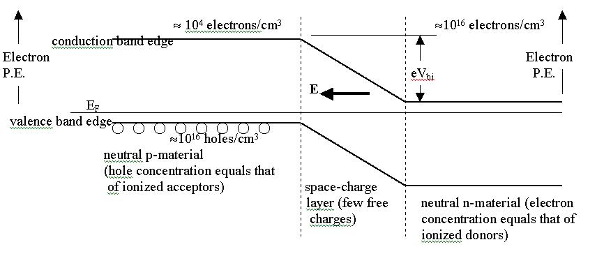
P-type material. P-type silicon is doped with a group 3 element like boron, which readily accepts an extra electron to complete its bonding arrangement with surrounding Si atoms. An ionized acceptor is then negatively charged, and a vacancy is created in the valence band of Si (a 'hole' which is free to move about). Holes are effectively positively charged, due to the underlying positive charge of the Si nucleus. P-type Si is electrically neutral in its bulk regions, with equal concentrations of ionized acceptors and holes.
N-type material. N-type silicon is doped with a group 5 element like phosphorus, which readily donates an extra electron to complete its bonding arrangement with surrounding Si atoms. An ionized donor is then positively charged, and an electron is free to move about in the conduction band of Si. N-type Si is electrically neutral in its bulk regions, with equal concentrations of ionized donors and electrons.
P-N junction. Where a p-and n-region meet there is a junction. Close to the junction we have ionized donors on one side and ionized acceptors on the other side. We may think of this as the electrons from the donors having landed on the acceptors. The region of ionized impurities is called the space-charge layer (SCL). There are very few free charge carriers (either electrons or holes) in the SCL. There is an electric field in the SCL, and a potential difference Vbi across it under no bias. In the bulk n material there is a large electron concentration, but a the edge of the SCL it drops rapidly. This means that there is a strong 'diffusion tendency' of electrons in the n-region to diffuse over to the p-side. However there is an electric field in the SCL which forces the electrons back to the n-side. At equilibrium, the diffusion and drift currents are equal and opposite, and no net current flows across the junction. (Drift current is due to the electric field acting on free charges.) With no bias, there is a potential difference between the bulk p region and the bulk n-region. The potential is more negative on the p-side (due to the negatively ionized acceptors being closer) and more positive on the n-side (due to the positively ionized donors in the SCL).
Forward bias on the p-n junction. A forward bias is applied to have current flow from the p-side to the n-side through the device (positive current enters the p-side terminal and leaves at the n-side terminal.) The forward bias reduces the potential difference between the two sides. (Colloquially, it reduces the size of the 'hill' the electrons have to climb. Holes are sometimes thought of as bubbles in a liquid, and in this picture, holes have to 'climb down' the hill.)
The lowering of the hill means that the electric field is smaller, and the diffusion current of electrons and holes now prevails over the drift current: a significant number of electrons have enough kinetic energy to climb the hill (the electron PE is higher on p side, even though the electric potential is lower there).
Reverse bias on the p-n junction. Reverse bias raises the potential difference across the junction, so diffusion current cannot prevail, and very little 'stray' current flows through the device.
Summary. The bipolar p-n junction is a diffusion driven device,
due to the large gradient in free charge concentration in the space-charge
layer. When forward bias lowers the potential difference between the two
sides, the forward current which flows through the device is dominantly
diffusion current.
Galvanic Cells.
Electrolytic half cells. As an example, let us imagine a copper electrode in a CuSO4 aqueous solution. In all thermodynamic systems the entropy tends toward a maximum as we approach equilibrium. Under conditions of constant temperature and pressure, the gibbs free energy G tends toward a minimum1. We are interested in copper going into solution:
Cu(s) <--> Cu(++(aq))
The Gibbs free energy in solid Cu is taken as zero, and in standard aqueous solution we find2 G(Cu2+(aq)) = 15.53 kcal/g-mol, or 0.676 eV/ion. Since G is lower in the solid, we expect some Cu++ ions to migrate to the solid electrode, charging the electrode positively.
At equilibrium, the Cu electrode is positively charged, surrounded by a region of net negative charge. This is due to [SO42-] > [Cu2+] close to the electrode. There is a gradient of both ions near the electrode which diminishes to zero a short distance away after which we have the electrically neutral CuSO4 solution.
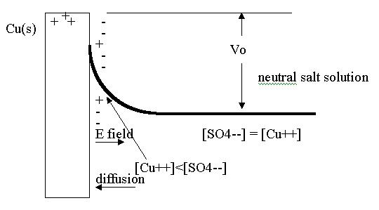
Thus there is a potential difference +Vo between the electrode and the neutral bulk solution. Close to the electrode there is an electric field which diminishes to zero as we reach the neutral bulk solution. The net current of Cu+2 ions is zero at equilibrium, with diffusion and drift currents cancelling out. The potential difference Vo is called the 'half-cell potential' (or standard reduction potential). For Cu(s) - CuSO4 example3, Vo = +0.34v . (This is for dilute aqueous solutions, and is independent of the negative ion in the solution: it could be NO32- instead of SO42-).
In a reversible process, (no entropy increase) the change in G equals the work done on the system by other than PD V work. If we imagine a Cu2+ ion being slowly moved by an external agent from solution to the electrode, the change in its gibbs function is exactly the work on it by the agent. For an ion next to the electrode Wnext = G(s) - G(aq) = - .68 eV. This says .68 eV is liberated when an ion next to the electrode plates out.
At equilibrium, however the net work done on a Cu ion taking it from the neutral solution through the potential difference and then depositing it on the electrode will be different. It must include the electrical work to move the two charges up to the potential Vo, namely 2 eVo
Wother = -.68 eV +2 eVo.
If this net work is negative, an ion at equilibrium making this trip would release energy. If the net work is positive, a copper atom going into solution would release energy. At equilibrium, this work must be zero, so we conclude that Vo = 0.34 v as indicated in the tables of half-cell potentials.
Summary. Half-cell electrolytic systems with a solid in an aqueous
salt solution develop a potential difference between the solid and the
neutral salt solution. Next to the electrode there is a concentration gradient
of salt ions. At equilibrium, there is no flow of ions onto the electrode.
This is a standoff between the electric field repelling ions and a diffusion
dendency of the ions to move toward the electrode.
The galvanic cell : two half-cells. When we join two suitable half-cells like copper and zinc electrodes and a salt solution we obtain a proper galvanic cell. The Daniell cell4 consists of these electrodes in a sulfate solution. We have established the half-cell emf of the Cu half is +.34 v, and now briefly examine the Zn half. In aqueous solution, the Gibbs free energy G of Zn++ is 35.15 kcal/g-mol or -1.53 eV/ion.
In this case the solid Zn from the electrode spontaneously goes into solution, lowering the system G, and charging the Zn electrode negatively. The half-cell potential Vo is -0.765 v.
Digression. We might briefly ask why the two similar metals behave so differently. The melting point of Cu is 1083 oC, while the melting point of Zn is 420 oC. Thjis suggests it is much more difficult to liberate a Cu atom from its solid lattice, than for a Zn atom. Similar information is conveyed by the Gibbs free energy of gaseous Cu and Zn. For gas phase Cu, G = 72.04 kcal/g-mol (3.13 eV/atom), while for Zn it is 22.69 kcal/g-mol (0.987 eV/atom). The gas-phase G is mostly the energy required to sublime an atom from the solid to the gas phase.
The difference in G in the gas phase turns out to be almost the same
as the difference in G for the aqueous ions. This suggests that the big
difference comes in the sublimation energy needed. Copper appears to have
a more stable lattice, seen by the higher melting point and also the higher
gas phase G. The two metals have slightly different ionization energies
(around ½ eV), and presumably require a similar energy to form the
ion in aqueous solution. So as a working conjecture we might say the Daniell
cell emf is due to solid copper being harder than solid zinc.
Galvanic cell electric fields. If a high resistance wire is connected
between the copper and zinc electrodes of a Daniell cell, current will
flow, nominally positive, from the Cu electrode to the Zn electrode. It
is worthwhile noting that in this case the line integral of the electric
field around a closed circuit does equal zero, as we would naively expect.
The key to understanding this situation is that current flows against the
electric field near one of the electrodes. When the wire is connected,
the potential difference between Cu and Zn electrodes is reduced somewhat.
This permits diffusion to drive Cu++ ions toward the Cu electrode (against
the electric field), while at the other electrode negative ions are diffusing
toward the Zn electrode while being opposed by the electric field next
to that electrode.
Similarities between the galvanic cell potential difference and that of the p-n junction.
In a p-n junction we have a built-in potential difference at equilibrium which depends on the concentrations of dopants Nd and Na (Nd for the n-side and Na for the p-side), as well as ni, the intrinsic electron concentration with no dopants:
Vbi = kT/q ln(NaNd/ni2) .
For a galvanic cell, we have an emf which also depends on kT/q and the log of concentrations via the Nernst equation:
E = Eo kT/q ln ([Cu++]/Zn++]) ,
where Eo is the emf under standard conditions (1 atm, 25
oC,
1 M solutions).
References
1. D. V. Schroeder, An Introduction to Thermal Physics, Addison-Wesley, (2000), Sect 5.2
2. Handbook of Chemistry and Physics, 56th Ed. (1976) p. D-67, ff.
3. R. Chang, Chemistry, 4th Ed. McGraw-Hill (1991), p. 785
4. A. Sommerfeld, Thermodynamics and Statistical Mechanics, Academic
Press, N. Y (1964), Sect 18.