Name: John D'Mura,
New Mexico State University at Carlsbad Address: 1500
University Dr.
Phone: (505) 234-9345 Home (505) 885-6004 Fax: (505)
885-4951
E-mail jdmura@cavern.nmus.edu
Low Cost Apparatus Competition
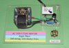
Apparatus Title: An AC, Shaded Pole, Induction Motor
for the Overhead projector or table top display.
 Abstract:
Early AC induction motors used a two-phase "rotating pole" mechanism to
produce rotation. Single phase, self-starting motors make use of a variety
of techniques to produce a torque to begin rotation. In the "shaded pole"
type of motor, off-set, closed coils, called shaded poles produce a slight
torque to begin the rotation. This demonstration apparatus uses the stator
and windings of a 2 pole motor and a hand made brass cage to act as the
rotor. The apparatus demonstrates several aspects of induction, Lenz's
Law and phase relationships in "rotating pole" type motors.
Abstract:
Early AC induction motors used a two-phase "rotating pole" mechanism to
produce rotation. Single phase, self-starting motors make use of a variety
of techniques to produce a torque to begin rotation. In the "shaded pole"
type of motor, off-set, closed coils, called shaded poles produce a slight
torque to begin the rotation. This demonstration apparatus uses the stator
and windings of a 2 pole motor and a hand made brass cage to act as the
rotor. The apparatus demonstrates several aspects of induction, Lenz's
Law and phase relationships in "rotating pole" type motors.
Equipment required to construct apparatus:
-
AC motor stator with windings (used or scrap, under $15),
-
miscellaneous sections of brass or copper rod and telescoping
tubing (under $ 10),
-
miscellaneous scraps of Plexiglas,
-
nuts and bolts and solder. See description of construction
details
Total cost..........................................................................Under
$ 40.00
Sketch of the apparatus: Find figures for this talk and
captions at;
http://www.geocities.com/b5lazer/Physics/ .
A complete description of the apparatus is desirable:
See construction details in the following article.
An AC, Shaded Pole, Induction Motor for the Overhead
Projector or Table Top Display
Introduction
With the serendipitous discovery of electromagnetism by
Hans Christian Oersted in 1820, began a revolution to invent electrical
rotation devices. Just one year later Michael Faraday had invented the
first primitive electromagnetic motor.[1] Faraday's subsequent invention
of the DC generator set off a flurry of experimentation worldwide. The
history of the development of electric power and electric motors is a sinuous
trail with hundreds of players on two continents racing to generate and
use electric power. Many researchers, entrepreneurs and tycoon barons worked
independently and sometimes-in concert to make the electric to make electric
power and the electric motor a tool of society.
In the 1840's several independent workers developed DC
motors. It was the dream of Nikola Tesla to create brush-less dynamos and
motors using Alternation Current that served as the historic focus of a
turning point in history.2 After demonstrating a polyphase AC motor in
1884 Tesla was granted a broad patents for the use of "rotating magnetic
fields" in electrical devices in 1887.
Tesla sold his patents to George Westinghouse in 1888
thus beginning the "War of the Currents" pitting Thomas Edison's DC power
systems with Westinghouse backed AC power generation and distribution.
The single-phase induction motor was an important goal
of the Westinghouse group because Tesla's original [2] phase designs were
not compatible with existing dynamo equipment. Although Tesla had developed
the "split phase" motor years earlier, he worked with the Westinghouse
group as a consultant through 1889 to help refine the design which was
already covered by his earlier patents.1 Following this time the trend
was toward building bigger and more powerful 3 phase motors for industrial
use. Development of smaller motors including the "Squirrel-cage" continued
for decades.[1]
Fractional horsepower motors were needed in household
applications. Small versions of bigger motors were used but by the 1940's
simple motors such as the shaded pole design were produced in mass quantities
for use in house hold appliances such as washing machines, ventilators
and record players.[3]
Operation of Shaded Pole Motors.
 The
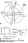
operation of all single-phase AC motors depends on a primary winding and
an auxiliary or secondary winding to provide a "starting torque". The auxiliary
windings are located 90 electrical degrees out of phase with the primary
winding.[4] The resulting shift in phase provides the torque needed to
make the motor self-starting.[5] (See Figure 2).
The
operation of all single-phase AC motors depends on a primary winding and
an auxiliary or secondary winding to provide a "starting torque". The auxiliary
windings are located 90 electrical degrees out of phase with the primary
winding.[4] The resulting shift in phase provides the torque needed to
make the motor self-starting.[5] (See Figure 2).
In a shaded pole motor the auxiliary winding is replaced
by one or two closed turns of heavy copper wire embedded in one side of
each stator pole.[4] (See figure 3). 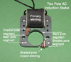 That
part of the stator that is not encircled by the copper turns is the main
stator pole and that part that is covered by the copper turns is termed
the "shaded pole" The operation of the shaded -pole motor is described
in "Electric Motor repair".[4]
That
part of the stator that is not encircled by the copper turns is the main
stator pole and that part that is covered by the copper turns is termed
the "shaded pole" The operation of the shaded -pole motor is described
in "Electric Motor repair".[4]
"On starting, a current is induced into the shaded poles
from the main poles. The shading coils establish a magnetic field that
is out of phase with that established by the main fields, and a shifting
field is produced sufficient to give the desired starting torque. When
the motor reaches speed the effect of the shading coils is negligible."[4]
That is, after the maximum flux is established in the main
stator pole a strong current builds in the shading coil. The resulting
flux around the shaded pole is in the same direction as was previously
established in the main stator pole. This shifting of the magnetic pole
from the main pole to the shaded pole position drags the rotor (by induction)
over the shaded pole and the pattern repeats each half cycle resulting
in rotation of the rotor.
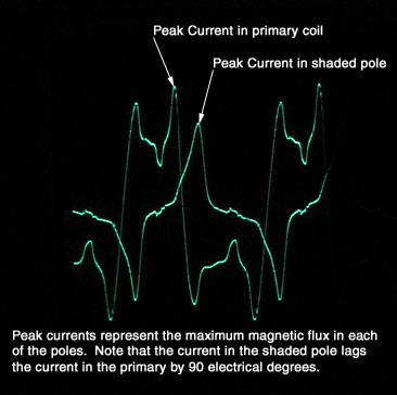 Using
current probes and an oscilloscope the changing currents in the main pole
and shaded pole illustrates the phase relation of the currents producing
the "rotating" magnetic field. (See figure 4).
Using
current probes and an oscilloscope the changing currents in the main pole
and shaded pole illustrates the phase relation of the currents producing
the "rotating" magnetic field. (See figure 4).
Building the Apparatus
The first prototype of my apparatus used the stator of
a 4 pole motor along with a hand-made cage made of copper. I used a hand
made wooden gig to hold the 8 rotor arms for soldering. It operates very
smoothly and can be seen as (See figure 13). The main drawback was that
the shaded poles are completely covered by the windings and can be viewed
only if the stator is held at an angle.
In later versions I decided to use a two-pole stator because
the shaded poles are clearly visible. The stator I chose for my competition
machine came from a toy rock tumbler purchased for $1 at a garage sale.
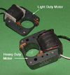 In
choosing a stator the thickness of the laminated portion gives a rough
indication of the power of the motor. The general rule is the thicker the
stator the greater the power. I could compare stators by measuring the
no load resistance of the primary coil. I found that stator coils of 5
or 6 ohms were too powerful and tended to heat up very quickly. Stator
coils with resistance between 30 and 50 ohms were too weak to produce good
results. The competition stator coil has a resistance of about 13 ohms.
(See figure 5).
In
choosing a stator the thickness of the laminated portion gives a rough
indication of the power of the motor. The general rule is the thicker the
stator the greater the power. I could compare stators by measuring the
no load resistance of the primary coil. I found that stator coils of 5
or 6 ohms were too powerful and tended to heat up very quickly. Stator
coils with resistance between 30 and 50 ohms were too weak to produce good
results. The competition stator coil has a resistance of about 13 ohms.
(See figure 5).
 The
second step is building the cage itself. I chose a ribbed design that would
illustrate the closed loops required for induced currents in the rotor.
(See figure 6)
The
second step is building the cage itself. I chose a ribbed design that would
illustrate the closed loops required for induced currents in the rotor.
(See figure 6)
The choice of materials is the first step. Having run
out of copper stock I chose solid brass rod of diameter 3/16's inch for
the ribs. Since eight ribs have to be soldered to the hubs I calculated
that the hub should be in the range of 1/4 inch in diameter. I made the
hubs using telescoping brass tubing. After choosing the widest diameter
tubing needed, I soldered smaller tubing into a mass, leaving the smallest
tube at the center open to accept the needle (pivot)of the jewel vee bearing.
I then placed a section of the tubing in a drill press and cut it off using
a jewelers saw. (A little help 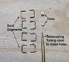 from
the machine shop would help this process.) I calculated the length of each
rib segment taking into account the radius of the hub, the desired height
of the cage, the radius of the hole in the stator and some clearance for
rotation. The competition apparatus has rib segments that are about 11/4
inches in length. (See figure 7.)
from
the machine shop would help this process.) I calculated the length of each
rib segment taking into account the radius of the hub, the desired height
of the cage, the radius of the hole in the stator and some clearance for
rotation. The competition apparatus has rib segments that are about 11/4
inches in length. (See figure 7.)
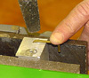
I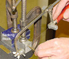 n
order to insure uniform length I drilled a hole in a milled block of aluminum
11/4 inches thick. The hole must penetrate the block for removal of the
cut segments. I placed the aluminum block in a vise with a backing block
to hold the brass stock. I cut each segment with a jewelers saw and filed
each end of the segment flat. (See figure 8).
n
order to insure uniform length I drilled a hole in a milled block of aluminum
11/4 inches thick. The hole must penetrate the block for removal of the
cut segments. I placed the aluminum block in a vise with a backing block
to hold the brass stock. I cut each segment with a jewelers saw and filed
each end of the segment flat. (See figure 8).
 To
bend each segment into a "C" shape I drilled a hole in an aluminum block
to the depth of the desired rib radius. After inserting the segment into
the hole I used a small hammer to bend the segments at the desired radius.
The ribs must have right angles and be flat. (See figure 9).
To
bend each segment into a "C" shape I drilled a hole in an aluminum block
to the depth of the desired rib radius. After inserting the segment into
the hole I used a small hammer to bend the segments at the desired radius.
The ribs must have right angles and be flat. (See figure 9).
To assemble the cage I had the school's machine shop make
an aluminum gig with a center hole of diameter 1/4 inch and 8 radiating
grooves to hold the bent rotor segments. Working from the top, I supported
the upper hub with a cut segment of ceramic tubing extracted from a crucible
holder donated by the chemistry department. After placing the ribs in the
grooves braced against the lower hub I placed the upper hub on the ceramic
segment and used fine steel 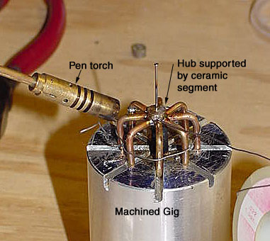 wire
to pull the ribs against the upper hub. After careful application of flux
paste I used a pencil torch to solder upper hub to the ribs. (See figure
10). I then turned the cage over and repeated the soldering process. I
used short segments of straight pins through the hubs and used epoxy to
glue them in place to provide pivots on each end of the cage.
wire
to pull the ribs against the upper hub. After careful application of flux
paste I used a pencil torch to solder upper hub to the ribs. (See figure
10). I then turned the cage over and repeated the soldering process. I
used short segments of straight pins through the hubs and used epoxy to
glue them in place to provide pivots on each end of the cage.
The next step was to mount the stator on a sheet of Plexiglas
used as the base. I used the existing holes of the stator as drill guides
to drill holes in the Plexiglas. I used nylon spacers to provide an air
space between the motor and the base. To locate the position of the jeweled
bearing I wrapped several lengths of paper around the cage until it fit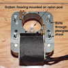 snugly
in the hole in the stator. The pin pivot marked the drill point for the
bearing. The bearing, taken from the movement of an old analog voltmeter
was centered and mounted on a short nylon spacer. Epoxy was used to glue
it in place. (See figure 11).
snugly
in the hole in the stator. The pin pivot marked the drill point for the
bearing. The bearing, taken from the movement of an old analog voltmeter
was centered and mounted on a short nylon spacer. Epoxy was used to glue
it in place. (See figure 11).
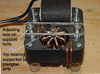 Long
bolts through the stator support a strip of Plexiglas holding the upper
bearing. The bearing height is adjusted by raising or lowering the nuts
on the support bolts. (See figure 12).
Long
bolts through the stator support a strip of Plexiglas holding the upper
bearing. The bearing height is adjusted by raising or lowering the nuts
on the support bolts. (See figure 12).
To finish the project I wired in a momentary contact switch
on to a separate shelf of Plexiglas mounted on nylon spacers. The machine
can be used as a tabletop demonstration or on the overhead projector for
larger audiences.
Note: stock metal, tubing and jeweled bearings
are available through Small Parts Inc. 13980 N.W. 58 Court P.O. Box 4650,
Miami Lakes, Fl 33014-0650 or call 1-800-2204242 for immediate service
or a catalog.
Bibliography
1. Author Unknown, ITQ Historical Archive, http://pixii.com/apparatus.htm
2. Cheney and Uth. TESLA, Master of Lightning. New York:
Barnes & Nobel Books, 1999.
3. Author Unknown, A Short History of Electric Machines,
http://historia.et.tudelft.nl/pub/art/machines.php3
4. Rosenberg and Hand. Electric Motor Repair, Third Edition.
New York: Holt, Rinehart and Winston, 1987.
5. McGraw-Hill encyclopedia of science & technology.
8th ed., "Induction Motors.
Other Useful References
Electricity: http://www.ioa.com/~micron/002-Electricity.html
Carlson Nikola Tesla: http://www.eh.net/Conference/carson.html