Advanced Laboratory / Lecture Demonstration Competition
A Modified Eclipsing Binary Star System Model
Absract: In the October 1979 issue of TPT, a model of an eclipsing binary star system was presented by Dr. R. H. Bloomer. A modified model is herein presented which is relatively easy to construct and has a number of additional features: it is*described as an adjustable rotating, adjustable intensity, adjustable position, double light sources in conjunction with a computer and/or calculator linked light sensing device to yield light intensity curves simulating those of an eclipsing binary star system.
Equipment required to construct apparatus:
Quantity Description Source Cost
A modified model is herein presented which is relatively easy to construct and has a number of additional features: it is described as an adjustable rotating, adjustable intensity, adjustable position, double light sources in conjunction with a computer and/or calculator linked light sensing device to yield light intensity curves simulating those of an eclipsing binary star system.
The adjustable rotation is accomplished by using an ordinary circulation fan motor controlled by a variable speed fan control (a variable autotransformer [Variac/PowerStat] may also be used). Minimum revolution rate is about 5 rpm and higher rates are possible, as desired, with due attention to limiting safety factors. This variation allows a simulation of different binary star system rotation velocities.
Using light dimmer switches connected to brushes/contact rings to each light bulb, the light intensity may be, individually, varied for each of the two light bulbs. Using light bulbs of the same size, the intensity may be the same or different for the desired simulation intensity. For bulbs of different size, for instance, simulating a white dwarf and red giant, their intensities may be adjusted accordingly.
Position of the "stars"(light bulbs) to the plane of the "observer" or sensor is dependent upon the placement of the sensor, which is accomplished by using a lab stand and appropriate clamp. Alternative, the cubic housing may be shimmed to tilt the plane of the rotating "stars" with respect to the sensor or observer. The "stars," relative to one another, may be adjusted by sliding along the wooden rotating arm, the center of which comprises the center of rotation and the "center of gravity" for the "stars." Each light bulb ("star") may also be raised vertically to match the center of the other light bulb, should the bulbs be different in size. This is normally not a large adjustment, but allows a more realistic simulation with the reservation that the lamp base and mount contribute to the amount of opacity for one of the eclipses.
In the original paper, a photometer was constructed using a phototransistor in conjunction with a strip chart recorder. Although these may still be available, commercially produced equipment is used with the modified model. Accompanying the Texas Instrument CBL system is a light sensor, which, when used in conjunction with a program for light intensity versus time on a compatible TI calculator (in this case, a TI-92), connected to the CBL, produces quite acceptable data for the light intensity curves. The curves may be noted either on the calculator screen or the data may be transferred to a computer for manipulation in a spreadsheet.
More sensitive light sensors are available in the TeamLabs PSL system, using either the photometric probe or the radiometric probe. Each has the "disadvantage" of being sufficiently sensitive to pick-up the 60 Hz sinusoidal variation in the light sources within three meters of such sources. The accompanying software for the interface is very convenient for generating the light curves, and, as in the case of the CBL data, may be transferred to a spreadsheet.
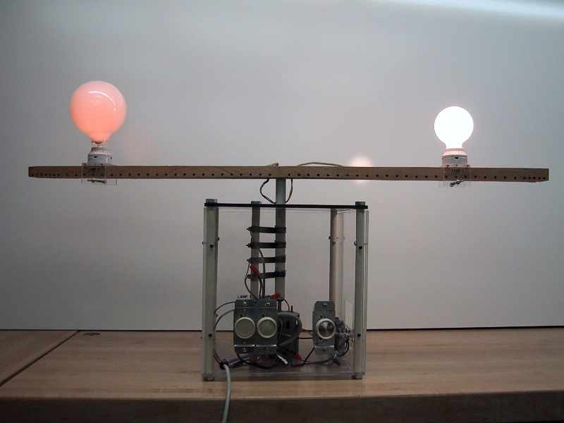
This particular model of the eclipsing binary star model is easy to transport and utilize just as a visual model. With a white background, human observers (students) often indicate a degree of amazement that a light source can cast a shadow due to another brighter light source. Otherwise, the model functions as that of the original with additional variations contributing to the light curves due to the additional adjustable properties introduced which, in turn, are intended to relate to a more physically realistic relation to an actual eclipsing binary star system.
Construction
SAFETY FIRST
Across the bottom face, diagonals are lightly drawn, placing the center for mounting the fan motor. This motor is of the type found in a typical box circulating fan, 20 inch variety. These motors generally have mounting bolts and nuts on the rear side, thus drilling coordinating holes in the base plate allows a secure mounting of the motor in the center.
Using the same procedure for centering, a ¾ inch hole is drilled in the top plate. This may have to be slightly over-sized to accommodate the ¾ inch PVC pipe, 25 cm length, which is the vertical extension of the motor shaft.
At each corner of the top and bottom plates, ½ inch, centered, from the edges, a ½ inch hole is drilled for the eight ½ inch hex, one inch bolts so that each top and bottom plate may be attached to the cube.
Depending on the radius of the motor, an additional vertical section of ½ (ID) PVC pipe, drilling ½ inch holes in the top and bottom plates accordingly, is placed about one inch from the edge of the motor at the left front corner of the cube. This pipe serves as the support for the electrical contact brushes that will make contact to the vertical (3/4 inch PVC pipe) shaft of the motor. Two ½ inch hex bolts, as at the corners, secure this section. Four, half inch wide, six inch long metal bands (from metal banding, used in securing lading, cleaned to bare metal), with about two inches bent and bolted around the ½ inch PVC pipe, become the electrical brushes. A second bolt and nut is used at that end to provide more stability.
On the ¾ inch PVC vertical motor shaft, which is secured to the metal motor shaft by drilling a hole through both the metal and PVC pipe and bolting, using a rubber stopper to center the metal shaft in the PVC pipe, four metal rings, cut from a ¾ inch inside diameter iron pipe, are placed (not easy to do), coordinately, to match the metal brushes. Set the vertical shaft, with the top plate of the cube in place, and mark a point ½ inch above top of plate for wire holes, then remove and drill, through, both sides, centered. Above each metal ring, a 3/16 inch hole is drilled, two on one side, upper, two on one side, lower, opposite to those on the upper for electrical wires. Then, two 75 cm lamp cords, one for each lamp, are threaded through the holes and soldered to the iron rings.
Mounted on the top of the vertical motor shaft is a 110 cm 1 x 2 pine wood rotating arm, rabbited out one half the thickness leaving ¼ inch sides (reduces mass), with a ¾ inch hole drilled at the center for the hex bolt and two ¼ inch holes 1 cm to each side of this hole for the electrical wire. The wires from the vertical shaft are threaded through these holes in the wood for wiring the lamp bases.
The plexiglas mounts for the porcelain lamp bases are 5 ½ cm wide consisting of three pieces, 5 ½ cm, 7 cm, and 7 cm long, secured by ½ inch hex screws, in a upside down U shape. The lamp bases are secured to the mounts using 6/32 - ½ inch machine screws in holes drilled in the*plexiglas (which acts as the nut). Three inch bolts with wing nuts supply the frictional hold for the lamp mounts on the rotating wooden arm.
The lamp dimmer switches are each mounted to the left of the removable faceplate of the cube and wired to the hot (black) side of the circuit and the second and fourth brushes. The first and third brushes are wired to the neutral side. These wires are then attached, using wire nuts, to the six foot power cord and plug. The fan motor speed control and switch is wired in series between the hot (black) side of the circuit and the motor and mounted on the right side of the removable faceplate. The other lead of the motor is connected to the neutral (white) side of the circuit.
Reference
1. R. H. Bloomer, Jr., The Physics Teacher, 17, 456 (1979).