32.3. Identify: Apply![]()
Set Up: ![]()
Execute: (a)![]()
(b)![]()
(c) ![]()
(d)![]()
Evaluate: f increases when ![]() decreases.
decreases.
32.7. Identify and Set Up: The
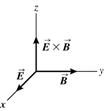
equations are of the form of Eqs.(32.17), with x replaced by z. ![]() is along the y-axis;
deduce the direction of
is along the y-axis;
deduce the direction of ![]()
Execute: ![]()
![]()
![]()
![]()
![]() is along the y-axis.
is along the y-axis. ![]() is in the direction of
propagation (the +z-direction). From this we can deduce the direction of
is in the direction of
propagation (the +z-direction). From this we can deduce the direction of ![]() as shown in Figure 32.7.
as shown in Figure 32.7.
|
|
|
|
Figure 32.7 |
|
![]()
![]()
![]()
![]()
Evaluate: ![]() are perpendicular and oscillate in phase.
are perpendicular and oscillate in phase.
32.12. Identify: ![]()
Set Up: The magnetic field of the earth is
about ![]()
Execute: ![]()
Evaluate: The field is much smaller than the earth's field.
33.25. Identify: When unpolarized light passes through a
polarizer the intensity is reduced by a factor of ![]() and the transmitted light is polarized along the axis of the
polarizer. When polarized light of intensity
and the transmitted light is polarized along the axis of the
polarizer. When polarized light of intensity ![]() is incident on a polarizer, the transmitted intensity is
is incident on a polarizer, the transmitted intensity is ![]() , where
, where ![]() is the angle between the polarization direction of the
incident light and the axis of the filter.
is the angle between the polarization direction of the
incident light and the axis of the filter.
Set Up: For
the second polarizer ![]() . For the third polarizer,
. For the third polarizer, ![]() .
.
Execute: (a) At point A the intensity is ![]() and the light is polarized along the vertical direction. At
point B the intensity is
and the light is polarized along the vertical direction. At
point B the intensity is ![]() , and the light is polarized along the axis of the second
polarizer. At
, and the light is polarized along the axis of the second
polarizer. At
point C the intensity is ![]() .
.
(b) Now for the last
filter ![]() and
and ![]() .
.
Evaluate: Adding the middle filter increases the transmitted intensity.
33.29. Identify: From Malus’s law, the intensity of the emerging light is proportional to the square of the cosine of the angle between the polarizing axes of the two filters.
Set Up: If the angle between the two axes is q, the intensity of the emerging light is I = Imax cos2q.
Execute: At
angle q,
I = Imax cos2q, and at the new angle a, ![]() I = Imax cos2a. Taking the ratio of the
intensities gives
I = Imax cos2a. Taking the ratio of the
intensities gives ![]() , which gives us
, which gives us ![]() . Solving for a yields
. Solving for a yields ![]() .
.
Evaluate: Careful! This result is not cos2q.
33.31. Identify: When
unpolarized light of intensity ![]() is incident on a polarizing filter, the transmitted light has
intensity
is incident on a polarizing filter, the transmitted light has
intensity ![]() and is polarized along the filter axis. When polarized light
of intensity
and is polarized along the filter axis. When polarized light
of intensity ![]() is incident on a polarizing filter the transmitted light has
intensity
is incident on a polarizing filter the transmitted light has
intensity ![]() .
.
Set Up: For
the second filter, ![]() .
.
Execute: After
the first filter the intensity is ![]() and the light is polarized along the axis of the first
filter. The intensity after the second filter is
and the light is polarized along the axis of the first
filter. The intensity after the second filter is ![]() , where
, where ![]() and
and ![]() . This gives
. This gives![]()
Evaluate: The transmitted intensity depends on the angle between the axes of the two filters.
35.3. Identify: Use ![]() to calculate the wavelength
of the transmitted waves. Compare the difference in the distance from A to P
and from B to P. For constructive interference this path difference is an
integer multiple of the wavelength.
to calculate the wavelength
of the transmitted waves. Compare the difference in the distance from A to P
and from B to P. For constructive interference this path difference is an
integer multiple of the wavelength.
Set Up: Consider Figure 35.3
|
|
The distance of point P from each coherent source is |
|
Figure 35.3 |
|
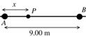
Execute: The path difference is ![]()
![]()
![]()
Thus ![]() and
and ![]() x must lie in the
range 0 to 9.00 m since P is said to be between the two antennas.
x must lie in the
range 0 to 9.00 m since P is said to be between the two antennas.
![]() gives
gives ![]()
![]() gives
gives ![]()
![]() gives
gives ![]()
![]() gives
gives ![]()
![]() gives
gives ![]()
![]() gives
gives ![]()
![]() gives
gives ![]()
All other values of m give values of x out of the allowed range.
Constructive interference will occur for ![]()
Evaluate: Constructive interference occurs at the midpoint between the two sources since that point is the same distance from each source. The other points of constructive interference are symmetrically placed relative to this point.
35.5. Identify: If the path difference between the two waves is equal to a whole number of wavelengths, constructive interference occurs, but if it is an odd number of half-wavelengths, destructive interference occurs.
Set Up: We calculate the distance traveled by both waves and subtract them to find the path difference.
Execute: Call P1 the distance from the right speaker to the observer and P2 the distance from the left speaker to the observer.
(a) P1 = 8.0 m
and ![]() . The path distance is
. The path distance is
![]() = 10.0 m – 8.0 m = 2.0
m
= 10.0 m – 8.0 m = 2.0
m
(b) The path distance is one wavelength, so constructive interference occurs.
(c) P1 = 17.0
m and ![]() . The path difference is 18.0 m – 17.0 m = 1.0 m, which is
one-half wavelength, so destructive interference occurs.
. The path difference is 18.0 m – 17.0 m = 1.0 m, which is
one-half wavelength, so destructive interference occurs.
Evaluate: Constructive interference also
occurs if the path difference 2![]() , 3
, 3![]() , 4
, 4![]() , etc., and destructive interference occurs if it is
, etc., and destructive interference occurs if it is ![]() /2, 3
/2, 3![]() /2, 5
/2, 5![]() /2, etc.
/2, etc.
35.19. Identify: Eq.(35.10): ![]() . Eq.(35.11):
. Eq.(35.11): ![]() .
.
Set Up: ![]() is the phase difference and
is the phase difference and ![]() is the path difference.
is the path difference.
Execute: (a) ![]()
(b) ![]() .
. ![]() .
.
Evaluate: ![]() and
and ![]() .
.
36.1. Identify: Use
![]() to calculate the
angular position
to calculate the
angular position ![]() of the first minimum.
The minima are located by Eq.(36.2):
of the first minimum.
The minima are located by Eq.(36.2): ![]()
![]() First minimum means
First minimum means ![]() and
and ![]() and
and ![]() Use this equation to
calculate
Use this equation to
calculate ![]()
Set Up: The central maximum is sketched in Figure 36.1.
|
|
Execute:
|
|
Figure 36.1 |
|
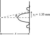
![]()
Evaluate: ![]() is small so the approximation used to obtain Eq.(36.3)
is valid and this equation could have been used.
is small so the approximation used to obtain Eq.(36.3)
is valid and this equation could have been used.
36.3. Identify: The
dark fringes are located at angles ![]() that satisfy
that satisfy ![]()
Set Up: The
largest value of ![]() is 1.00.
is 1.00.
Execute: (a)
Solve for m that corresponds to ![]() :
: ![]() . The largest value m can have is 113.
. The largest value m can have is 113. ![]() ,
, ![]() , …,
, …, ![]() gives 226 dark
fringes.
gives 226 dark
fringes.
(b) For ![]() ,
, ![]() and
and ![]() .
.
Evaluate: When
the slit width a is decreased, there are fewer dark fringes. When ![]() there are no dark fringes and the central maximum completely
fills the screen.
there are no dark fringes and the central maximum completely
fills the screen.
36.5. Identify: The
minima are located by ![]()
Set Up: ![]() .
. ![]() .
.
Execute: The
angle to the first minimum is ![]() = arcsin
= arcsin![]() = arcsin
= arcsin![]()
So the distance from the central maximum to the first minimum is
just ![]()
![]()
Evaluate: ![]() is greater than 1, so only the
is greater than 1, so only the ![]() minimum is seen.
minimum is seen.