30.7. Identify: ![]() and
and ![]()
Set Up: ![]()
Execute: (a) ![]()
(b) The average flux through each turn is ![]()
Evaluate: The self-induced emf depends on the rate of change of flux and
therefore on the rate of change of the current, not on the value of the
current.
30.9. Identify and Set Up: Apply ![]() Apply Lenz’s law to
determine the direction of the induced emf in the coil.
Apply Lenz’s law to
determine the direction of the induced emf in the coil.
Execute: (a) ![]()
(b) Terminal ![]() is at a higher potential since the coil pushes current
through from
is at a higher potential since the coil pushes current
through from ![]() to
to ![]() and if replaced by a battery it would have the
and if replaced by a battery it would have the ![]() terminal at
terminal at ![]()
Evaluate: The induced emf is directed so as to oppose the decrease in the
current.
30.11. Identify and Set Up: Use Eq.(30.6) to relate L to the flux through each turn of the
solenoid. Use Eq.(28.23) for the magnetic field through the solenoid.
Execute: ![]() If the magnetic field is
uniform inside the solenoid
If the magnetic field is
uniform inside the solenoid ![]() From
Eq.(28.23),
From
Eq.(28.23), ![]() Then
Then ![]()
Evaluate: Our result is the same as L for a torodial solenoid calculated in
Example 30.3, except that the average circumference ![]() of the toroid is
replaced by the length l of the straight solenoid.
of the toroid is
replaced by the length l of the straight solenoid.
30.13. Identify and Set Up: Use
Eq.(30.9) to relate the energy stored to the inductance. Example 30.3 gives the
inductance of a toroidal solenoid to be ![]() so once we know L we
can solve for N.
so once we know L we
can solve for N.
Execute: ![]()
![]()
Evaluate: L and hence U increase according to the
30.15. Identify: A current-carrying inductor has a magnetic field inside of itself and hence stores magnetic energy.
(a) Set Up: The magnetic field inside a solenoid is ![]()
Execute: ![]()
(b) Set Up: The energy density in a magnetic field is ![]()
Execute: ![]()
(c) Set Up: The total stored energy is U = uV.
Execute: ![]()
(d) Set Up: The energy stored in an inductor is ![]()
Execute: Solving for L and putting in the numbers gives
![]()
Evaluate: An inductor stores its energy in the magnetic field inside of it.
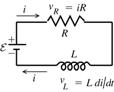
30.19. Identify: Apply Kirchhoff’s loop rule to the circuit. i(t) is given by Eq.(30.14).
Set Up: The circuit is sketched in Figure 30.19.
|
|
increases from its initial value of zero. |
|
Figure 30.19 |
|
Execute: ![]()
![]()
(a) Initially (t
= 0), i = 0 so ![]()
![]()
(b) ![]() (Use this equation rather than Eq.(30.15)
since i rather than t is given.)
(Use this equation rather than Eq.(30.15)
since i rather than t is given.)
Thus ![]()
(c) ![]()
(d) Final steady state means ![]()
![]()
Evaluate: Our results agree
with Fig.30.12 in the textbook. The current is initially zero and increases to
its final value of ![]() The slope of the
current in the figure, which is di/dt, decreases with t.
The slope of the
current in the figure, which is di/dt, decreases with t.
30.21. Identify: ![]() with
with ![]() The energy stored in
the inductor is
The energy stored in
the inductor is ![]()
Set Up: The maximum current occurs after a long time and is equal to ![]()
Execute: (a) ![]() so
so ![]() when
when ![]() and
and ![]()
![]()
![]()
(b) ![]()
![]() so
so ![]()
![]()
Evaluate: ![]() The time in part (a) is
The time in part (a) is ![]() and the time in part (b) is
and the time in part (b) is ![]()